By Peter S. Cartwright
Over the last 20 years, industry, in particular, has undergone a paradigm shift with regard to the need for water reuse. Words like "recycle", "resource recovery" and "conservation" have crept into the consciousness of process design and environmental engineers, even top management. This is partially fueled by pollution control legislation, but also out of a sense of environmental stewardship as well as the economic reality that throwing water away can be expensive over the long run.
The pressure-driven membrane separation technologies of microfiltration (MF), ultrafiltration (UF), nanofiltration (NF), and reverse osmosis (RO) have been in common use, in one form or another, since the early 1960s, with water purification applications comprising the vast majority of installations. A characteristic of these applications is that they are run at relatively low system recovery, defined as that percentage of the feedwater flow that passes through the polymer and exits as permeate.
While the contaminants in normal water supplies are relatively well understood in the context of membrane processes, that generalization doesn't apply when it comes to wastewater treatment. Many systems are one of a kind. And the traditional goal in contaminant removal applications is to make the contaminants go away, which means that system recoveries must be as high as possible.
As recovery goes up, the concentration factor (degree to which contaminants are increased in the feed/concentrate stream) increases exponentially. In most wastewater applications, there is a glaring lack of membrane processing experience, and this, coupled with the facts that no two wastewater streams are identical and may actually change in quality as a function of time, means that virtually every application requires thorough and comprehensive testing.
Fortunately, there are very few wastewater streams that will chemically attack the membrane polymers on the market today, so it's simply a matter of determining which polymer and device configuration is most appropriate for a given application, and to thoroughly test the stream to generate system design data.
Fundamentals
The primary goal in selecting the appropriate polymer is obviously to find the one that effectively removes the contaminants of interest. Secondarily, it is desirable to identify that which will produce the highest flux (permeate rate per unit area of membrane).
Microfiltration and ultrafiltration membranes are simply very fine filters in that if the pore is too small to allow passage of the contaminant, it is rejected (held back) by the membrane. The selection criteria for these polymers include the ability to efficiently manufacture them with a uniformly controlled pore size and to select materials that are chemically, physically and thermally stable.
In the case of nanofiltration and reverse osmosis, "size exclusion" is the removal mechanism for non-ionic contaminants and another mechanism is at work for the rejection of ionic contaminants. This latter mechanism is not completely understood; however, there are a limited number of very complex polymers that are effective as RO and NF membranes.
The membrane separation technologies of microfiltration (MF), ultrafiltration (UF), nanofiltration (NF) and reverse osmosis (RO) are defined by some membrologists on the basis of pore size. Other experts prefer to use definitions based on functions, as follows:
- MF is used to remove submicron suspended materials on a continuous or semi-continuous basis. The size range is from approximately 0.01 to 1.0 microns (100 to 10,000 angstroms). By definition, microfiltration does not remove dissolved materials.
- UF is a membrane process which removes dissolved non-ionic solute, typically organic materials (macromolecules). Ultrafiltration membranes are usually rated by "molecular weight cut-off," the maximum molecular weight of the dissolved organic compound (in Daltons) that will pass through the membrane into the permeate stream. These compounds are generally considered smaller than 0.01 micron (100 angstroms) in size.
- NF can be considered "loose" reverse osmosis. It rejects dissolved ionic contaminants but to a lesser degree than RO. NF membranes reject multivalent salts to a higher degree than monovalent salts (for example: 90% vs. 20%). These membranes have molecular weight cut-off limits for non-ionic solute in the range of 400 to 1000 Daltons.
- RO produces the highest quality permeate of any pressure driven membrane technology. Certain RO polymers will reject above 99% of all ionic solute, and have molecular weight cut-offs in the range of 50 to 100 Daltons.
Both NF and RO membranes reject salts using a mechanism that is not fully understood. Some experts endorse the theory of pure water preferentially passing through the membrane; others attribute it to the effect of surface charges on the membrane polymer reacting with the polarity of the water. Monovalent salts are not as highly rejected from the membrane surface as multivalent salts; however, the high rejection properties of thin film composite RO membranes exhibit very little difference in salt rejection characteristics. As indicated earlier, however, this difference is significant with NF membranes.
Engineering
In all cases, the greater the range of contaminants removal, the higher the pressure requirement to effect this separation. In other words, reverse osmosis, which separates the widest range of contaminants, requires an operating pressure an order of magnitude higher than microfiltration, which removes only suspended solids.
The water movement through membrane (to generate permeate) is known as "flux." It is a function of applied pressure, water temperature, and in the case of NF, RO, and some UF, the osmotic pressure of the solution under treatment. Flux rate is usually measured as GFD (gallons per square foot per day) or LMD (liters per square meter per day).
Increasing the applied pressure will increase the permeate rate; however, the higher flow of water through the membrane will tend to promote more rapid fouling, the single greatest cause of membrane failure. Membrane element manufacturers usually provide limits with regard to the maximum applied pressure to be used, as a function of feed water quality.
Heating the water will also increase the permeate rate, but this requires significant energy, and is generally not considered practical in most applications.
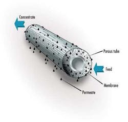
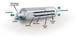
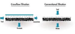
In a typical membrane system the feed stream enters the system (or membrane element), and as the stream passes along and parallel to the surface of the membrane under pressure, a percentage of the water is forced through the membrane polymer producing the permeate stream. Contaminants are prevented from passing through the membrane based on the polymer characteristics. This contaminant-laden stream exits the membrane system (or element) as the "concentrate" stream, also known as the "brine" or "reject".
The percentage of feed flow that passes through the membrane and becomes permeate is known as "recovery." This characteristic is set by the system designer based on the size of the feed pump selected. Typically, for water purification applications, recovery is set below 80%. As recovery is increased, the concentration of contaminants in the concentrate stream increases significantly.
For the processes of nanofiltration and reverse osmosis (and to a lesser extent, ultrafiltration) which deal with dissolved materials, a property of the solution known as "osmotic pressure" usually becomes the limiting factor. Osmotic pressure is a characteristic of all solutions (although more of a factor with dissolved salts), and is loosely defined as the resistance of the solvent portion of the solution to passage through the membrane. Osmotic pressure is a function of both the particular solute as well as its concentration. A specific test is almost always required to accurately determine osmotic pressure.
As recovery is increased (typically through the use of a flow restrictor or concentrate valve), with the resulting decrease in concentrate flow, the concentration of solute in the concentrate stream increases, resulting in increased osmotic pressure.
In an ideal system, all of the contaminants to be removed are separated by the membrane and exit in the concentrate stream. But, in reality, no membrane is perfect in that it rejects 100% of the solute on the feed side; this solute leakage is known as "passage". Expressed as "percent passage," the actual quantity of solute which passes through the membrane is a function of the concentration and kind of solute on the feed side.
Under high recovery conditions, with RO and NF, the concentration of salts on the feed side is increased, and therefore, because rejection is always a percentage of salts in the feed stream, the actual quantity of salts passing through the membrane also increases. Many applications demand that, in addition to a minimum concentrate volume, the permeate quality be high enough for the intended use. This "catch-22" predicament of permeate quality decreasing as recovery is increased can impose design limitations. Additionally, the increased osmotic pressure resulting as recovery is increased also imposes a design limit. Generally, pumping pressures in excess of 68 bar (1000 psi) are impractical for most applications.
Membrane Device Configurations
Since about 1955, and the creation of the first practical reverse osmosis membrane, membrane devices have evolved into many configurations. In an attempt to categorize them, the following types are generally accepted:
- Spiral Wound
- Plate and Frame
- Capillary Fiber
- Tubular
Spiral Wound
The spiral wound device is far and away the most common device configuration used in reverse osmosis and nanofiltration applications today. This is largely due to the fact that it is the least expensive configuration, resulting from its relatively high packing density (membrane surface area per unit volume), as well as the fact that it is a very competitively priced design. Because of the close spacing of the membrane leaves, this design has the greatest susceptibility to fouling.
Plate and Frame
The plate and frame membrane device has taken many shapes and sizes over the years, and has been used primarily for the technologies of microfiltration and ultrafiltration. The challenge of packing as much membrane area into as small a volume as possible, as well as problems associated with the sealing and gasketing to prevent leakage and cross-contamination, have limited use of this device. On the other hand, plate and frame elements are basically quite fouling resistant compared to the spiral wound configuration.
Capillary Fiber
This device consists of unsupported hollow fibers that have been extruded or spun from such polymers as polysulfone, polyethersulfone, polyacrylonitrile, polyvinylidene fluoride, or similar thermoplastic materials, which are manufactured with pore sizes in the microfiltration or ultrafiltration categories. The capillary fibers (also known as hollow fibers) are constructed with inside diameters of several millimeters and wall thicknesses of fractions of millimeters. In most cases, the permeate flow is from the inside of the fiber to the outside (lumen-feed), although the elements with the feed flow on the outside (and the permeate exiting from the lumen side) are considered to be more fouling resistant. Capillary fiber devices are beginning to be widely used for treating surface water sources to meet the new EPA drinking water regulations.
Tubular
These devices are differentiated from capillary fiber devices because they are constructed of a membrane-coated backing material (as with the spiral wound and plate and frame), which is wound into a tubular shape. Because this construction is more pressure tolerant than capillary fibers, the diameters of tubular devices can be made larger, thereby improving their tolerance to suspended solids. Most of the ceramic devices today are in the tubular configuration. The inside diameters of tubular devices typically range from about 7mm to 25mm, and the flow is virtually always lumen-feed. Tubular elements are made for all four membrane technologies (MF, UF, NF, RO).
From the perspective of cost and convenience, it is beneficial to pack as much membrane area into as small a volume as possible. This is known as "packing density". The greater the packing density, the greater the membrane area enclosed in a certain sized device, and (usually) the lower the cost of the membrane element (on the basis of permeate rate per membrane area). The downside of the high packing density membrane elements is their greater propensity for fouling.
Testing Options
All of these factors: recovery, osmotic pressure, permeate quality, recycle, etc., serve to underscore the value of testing the specific waste stream as thoroughly as possible. Because effluent streams often vary in analysis as a function of time, it is important that either a composite or a "worst case" sample be obtained for test purposes.
One or more of the following test procedures should be used when evaluating membrane technology with a particular effluent stream:
Cell Test
This uses small (approximately 15 square inches) pieces of sheet membrane mounted in a "cell" that exposes the membrane to the test solution using the crossflow mechanism. This test is effective for quick evaluation of a number of different membrane polymers to determine degree of separation.
Advantages:
- Fast
- Inexpensive equipment involved
- Only small quantities of test solution required
Disadvantages:
- Cannot indicate long term chemical effect of solution on polymer
- Does not provide engineering scale-up data
- Gives no indication of optimum membrane element configuration
- Does not provide data on fouling effects of test solution
Applications Test
This typically involves the evaluation of a 30-50 gallon sample of solution on a production-sized membrane element. The element is mounted in a test machine with the engineering features of production systems. For a given element, the test can be completed within 1-2 hours.
Advantages:
- Fast
- Provides scale-up data (flow, element efficiency, osmotic pressure as a function of recovery, pressure requirements, etc.)
- Can provide an indication of membrane stability
Disadvantages:
- Does not indicate long-term chemical effects
- Does not provide sufficient data on fouling effect of the test solution
Pilot Test
This usually involves placing a test machine (such as that used for the applications test) in the process operating on a "side-stream" for a minimum of 30 days.
Advantages:
- Accomplishes all of the functions of the applications test plus provides long-term membrane fouling and chemical stability data
Disadvantages:
- Expensive in terms of monitoring and time requirements
Conclusions
Hopefully, this paper has provided some insight into membrane technologies and their application to the almost limitless world of wastewater treatment and recycle applications.
About the Author: Peter S. Cartwright, PE, has been in the water purification and wastewater treatment industry since 1974. He has authored more than 125 papers, written several book chapters, holds three patents and has presented many lectures in conferences around the world. His company, Cartwright Consulting Co., specializes in the application of innovative treatment technologies to water purification, wastewater treatment and food/chemical processing.


