By Wes Byrne
The requirements for a working reverse osmosis (RO) system are few; it needs a pump, some membranes, vessels, and plumbing. But operating the system in a way that minimizes membrane fouling, maximizes membrane life, and does not suffer from hydraulic catastrophes can be challenging. This paper discusses an assortment of issues that have led to RO performance problems and the way those issues were resolved.
Pretreatment Issues
The most common cause of a complete failure of an RO application is inadequate pretreatment of the RO feed water. RO systems must be protected from incompatible contaminants, from the potential for scale formation, and from excessive fouling. Compromises made in the pretreatment methods, monitoring instrumentation, or quality of the equipment will usually result in operational problems in the downstream RO unit.
For example, a common compromise is to use the same flow control orifice on a multimedia filter discharge line to control both the filter backwash flow rate and the rinse flow rate performed after a backwashing. This method results in roughly the same flow rate being used for both steps. But where a backwash flow rate based on 12 gpm/ft2 of cross-sectional area is appropriate for obtaining 40% expansion of the media granules (@54oF), this same rinse flow rate will compact the media granules under a pressure drop exceeding 10 psid. This will tend to push any suspended particles still in the upper section of the media filters deeply into the media bed. Acceptable performance will only begin to be achieved until after the flow rate has been reduced to the normal service flow rate. If this only occurs while the filter is in service, much of the solids shed by the filters will end up in the RO cartridge prefilters and in the RO membrane elements.
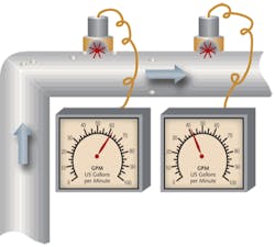
Another common mistake with media filters is not installing individual flow meters on each of multiple filters in parallel. Without these flow readings, there is no way to know if flow rates are balanced between the filters. If any particular filter starts to plug up with solids, more flow will divert to the other filters. Keep in mind that pressure gauges on each side of the filters will not indicate if one filter is plugging more than another if they are on common inlet and outlet lines, in spite of whether they read differently because of their inaccuracies.
If the media filter is not capable of providing water with a maximum silt density index (SDI) of 5, as noted as a requirement on some membrane manufacturers’ element specification sheet, a fatal mistake is to inject a polymeric filtration aid directly prior to the media filters. This mistake is particularly devious in how it appears to dramatically improve the effluent quality of the filters. What does not show up in the effluent turbidity or silt density index analysis is the residual polymer breaking through the filter.
Because of the polymer’s charge characteristics, it will permanently bond with the RO membrane. Any suspended solids will now attach to the polymer rather than migrating along the membrane surface. The rate of RO fouling will increase and cleanings will no longer restore original performance because it will not be possible to get the polymer off the membrane. The membrane elements will need to be replaced.
If media filters are not providing water of a sufficient quality, there are ways to improve their performance. A common misconception of pressurized filters is that they provide the best filtration at a flow rate of 5 gpm/ft2. Actually, filter performance will keep improving as the flow velocity is reduced until reaching the limits of the ability of the distribution laterals to prevent channeling.
It may be necessary to coagulate fine colloids upstream using a coagulant. If so, an inorganic coagulant should be employed, such as an aluminum product or ferric chloride. If these materials break through the media filter, they will also foul the downstream RO, but they can be cleaned. They should be used in a reaction tank of sufficient size to allow the reaction time necessary for the suspended solids to bind with the coagulant before getting to the media filters.
Chlorine Elimination
The polyamide thin-film membrane commonly used in most RO systems cannot handle chlorine. Some membrane manufacturers have promoted that their membrane could tolerate free chlorine equivalent to the exposure of 1 ppm over a period of 1000 hours before a doubling of salt passage would occur. This guideline has often been misinterpreted as meaning that it is acceptable to allow chlorine to occasionally contact the RO membrane as a means of reducing biological fouling. But membrane damage will soon occur if it is exposed to any amount of chlorine and will be cumulative. The damage will be worse if iron or other transition metals have fouled out on the membrane.
Sodium bisulfite is often used to reduce the chlorine concentration going into the RO. But sodium bisulfite will also react with dissolved oxygen in the water. Any excess bisulfite will tend to reduce the oxygen concentration, which increases the potential for increased anaerobic biological growth. These are the species responsible for heavy slime formations that can rapidly foul the systems. A definitive symptom of this is the sulfur dioxide, rotten-egg smell noted when membrane vessels are opened.
The optimum concentration of sodium bisulfite may be difficult to maintain. Sodium bisulfite present in the injection day tank or in chemical totes will degrade over time as it reacts with oxygen from the atmosphere. If sodium hypochlorite (bleach) is injected upstream, its concentration will also change depending on its age. Thus getting the correct bisulfite concentration injected relative to the chlorine concentration can be challenging.
ORP is a relatively inexpensive method of monitoring bisulfite dosage but its method may not directly reflect the residual chlorine concentration. Other variables can also impact its reading, especially pH.
When ORP is used to control bisulfite dosage on a continuously operating system, the results may be disastrous if the RO permeate returns back to an upstream feed tank when process water is not being demanded. During times of minimal usage, the increased concentration of RO permeate in the blended feed means that little alkalinity will be present. Added bisulfite will have an increased impact on the water pH and cause it to drop. The declining pH will cause the ORP reading to increase even if no chlorine is present. The control system will respond by adding even more bisulfite. The bisulfite injection pump will eventually max out on its dosage. All the excess bisulfite will deplete the oxygen in the water and a severe anaerobic bacterial outbreak will eventually result.
Scale Inhibition
The injection of a chemical scale inhibitor is typically the least expensive way to prevent scale formation in an RO system. These chemicals work by binding with the growing scale crystals, which reduces their particle growth rate. The smaller scale particles are more likely to remain suspended and exit the RO system in the concentrate stream.
A means of rinsing super-saturated salts from the RO prior to shutdown is essential to the success of this mechanism. The best method is to tee in pressurized permeate water with an automatic valve downstream of the inlet isolation valve to displace the water in the RO at shutdown. This has the added advantage of reducing the potential for anaerobic bacterial growth during shutdowns by reducing the concentration of anions in the RO, which are required for the anaerobic bacteria to proliferate. It also improves the quality of permeate during startup, which may mean that a permeate diversion system may not be needed at startups.
Homogeneous polyacrylic acid polymers are notorious for coming out of solution either due to over-injection, or due to a reaction with iron or aluminum. Sometimes they will even come out of solution with hardness if the injected chemical does not mix quickly at the point of injection. Blended inhibitors of two or more chemical components tend to perform better and are less likely to cause these problems.
Controls and Instrumentation
RO systems that will not be well attended by trained operators should have sufficient alarms and controls as to prevent catastrophic failures. The coordination of alarm conditions with system shutdowns is often performed with a human-machine interface (HMI). But if an HMI is employed, it is critical that either it is possible to make program modifications on-site, or that the HMI can be bypassed in case something goes wrong. An unforeseen problem in the program or a bad transducer should not prevent an RO system from being operated.
Accurate flow rate and pressure readings are critical to monitoring the performance of RO membrane elements. Flow transducers must be installed with a sufficient length of straight pipe upstream and downstream of the transducer as to meet the manufacturer’s recommendations. Otherwise, the meter may not perform under reduced flow conditions.
Flow meters should be calibrated based on an accurate measurement of the flow rate. This may be as simple as timing the rate at which a downstream storage tank fills. The incorporation of redundant flow meters will assist in noting when a transducer is not reading accurately.
Pressure transducers should not be located directly downstream of throttled valves. The high localized water velocity created by the valve will cause an aspiration effect that will result in the transducer reading less than the downstream pressure. Incorporation of valved tees at the transducer location will make it possible to check all readings using the same calibrated gauge.
Installation
It is common for the RO concentrate stream to be plumbed to a discharge drain located beneath the highest point of the membrane pressure vessels. Unless an automatic isolation valve or a vacuum breaking valve is installed on the concentrate line, a siphon will be pulled on the RO while it is shut down. Water will continue to flow through the line after shutdown and will pull a vacuum on the RO system.
This vacuum will cause water to partially drain from the RO pressure vessels. Victaulic-style couplings enable this draining because their standard gaskets allow air to be pulled into the system to displace the vacating water. Specialty gaskets can be purchased that maintain a better seal under vacuum conditions.
When an RO drains, the incoming air will carry bacteria and fungi spores into the membrane elements. This may contribute to fouling of the membrane elements. When the RO re-starts, water hammer may occur, which can break the fiberglass wrap and plastic anti-telescoping devices (ATDs) on the end of the elements.
A check valve that uses a lightly weighted spring (1-2 psi) may be teed in the top of the concentrate discharge line to allow air to be sucked into the line under vacuum conditions. It should be directed or plumbed in a way that does not spit water at personnel whenever the RO starts up.
About the Author: Wes Byrne has 30 years of experience in the design, engineering and maintenance of membrane based water treatment systems and is a trained educator. He has been instrumental in troubleshooting hundreds of membrane treatment problems and has developed several new applications for membrane systems.


