Microfiltration for Industrial Water Treatment in Power Generation
• Kansas City Power & Light Company’s La Cygne Generating Station stays ahead of the curve on membrane separation for high-purity water
by Brad BueckerMany industries require high-purity water for process operation, including steam generation. Purification of water from the initial source, such as a lake, river or groundwater, however, to a high-purity supply is not a single-step process. A very important procedure is removal of suspended solids, as otherwise these materials would foul and contaminate expensive equipment, at the potential cost of millions of dollars.
For decades, a primary method for suspended solids removal was clarification followed by single- or multi-media filtration with graded sand and supporting materials. Clarification/filtration is still a very viable method, but improvements in membrane manufacturing techniques are generating a shift towards microfiltration (MF) and ultrafiltration (UF) for suspended solids removal. This article outlines results from the replacement of an aging clarifier/filter system with a microfilter at Kansas City Power & Light Company’s La Cygne, KS, generating station. It’s an update of an article published in September 2005 in Power Engineering, a sister publication to Industrial WaterWorld that’s also published by PennWell Corp.
The La Cygne Experience
Some readers are no doubt familiar with the membrane filtration process of reverse osmosis (RO), for in the 1980s and 1990s this technology exploded in popularity as a retrofit technique ahead of existing demineralizers. La Cygne was no exception to the retrofit trend, and an RO system was placed in the Unit 1 (820 MW, supercritical boiler) makeup water system in the 1980s. As part of a major upgrade in the 1990s, an RO unit and downstream ion exchange system replaced the original flash evaporator in the Unit 2 (720 MW, 2,600-psig drum boiler) makeup train. Both RO systems were designed for 75% recovery with a maximum product water flow rate of 200 gpm.
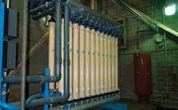
Even though the La Cygne boiler makeup systems were fitted with RO units, they continued to operate with the original clarifier/sand filters for suspended solids removal. By the early 2000s, combined chemical costs for the two clarifiers easily exceeded $100,000 annually, with labor and routine equipment repair costs adding considerably to that amount. In autumn 2004, based on reliable information from colleagues within the power industry, we tested a Pall Aria 4TM microfilter in the Unit 1 makeup water system to ascertain if it would produce cleaner water for RO feed and how, in turn, this would affect downstream equipment. Whereas most RO systems, at least for power plant applications, utilize spiral-wound membranes, the microfilter at La Cygne, and other machines like it, employs hollow fiber membranes where each module contains thousands of spaghetti-sized tubes. To produce the 300-gpm flow required by Unit 1 and auxiliary systems, 24-membrane modules (see Figure 2) were necessary.
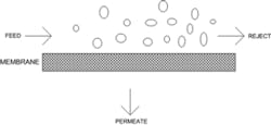
The microfilter process, like RO, operates via cross-flow filtration, in which raw water flows parallel to the membrane surface. Water that passes through the membranes and is purified is known as permeate. Not all water passes through each membrane, as a portion must flow along the surface to carry away suspended solids. This stream is known as the reject.
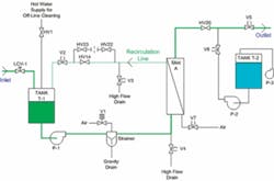
The treated water path through the membranes is outside-to-in, with the reject flowing along the external surface of the fibers. The basic system flow path is outlined in Figure 4.
Raw water enters tank T-1 for feed to the membranes. A level control gauge in the tank modifies inlet valve operation such that the tank maintains a constant level. Pump P-1 (rated at 20 HP) moves the raw water to the membranes. This pump is controlled by a variable frequency drive (VFD) to adjust the output based on the flow rate requested by the operator. Feed to the membranes passes through a basket strainer to remove any large solids that might otherwise clog the fiber inlet ends. Permeate flows directly to an existing storage tank, while reject flows back to tank T-1. Thus, no water is lost during normal operation. The standard mode of operation for our system is 10 minutes of water production followed by a one-minute air scrub/reverse flush (AS/RF) cycle to remove solids that collect on the membrane surfaces. The AS/RF utilizes previously-filtered water stored in tank T-2 for washing. The rinse water flows backwards through the membranes from inside-to-out. During the cycle, valve V7 opens to admit air to the membranes, which scours the membrane surface.
The only significant cost to operate the microfilter is for electricity that powers the P-1 and P-2 pumps. This cost is negligible compared to what was being spent on the clarifier and sand filters. The control system’s heart is a dedicated programmable logic controller (PLC) mounted on the pump skid, which is controlled from a personal computer in the Unit 1 laboratory.
Results & Lessons Learned
Makeup water for the boilers is taken directly from Lake La Cygne, where the typical turbidity ranges from 5-to-15 NTUs. We were given performance criteria that indicated the microfilter would remove particles down to 0.1 μm in size and produce an effluent turbidity of less than 0.1 NTU. Within an hour after system start-up, effluent turbidities had dropped to a range of 0.02-to-0.03 NTU, where they have consistently remained.
MF membrane pore sizes are larger than those of RO membranes, so only light pressure is required to push water through the membranes. Typical membrane inlet pressures on the La Cygne system range from 10 to 20 psi. The minimal pressure requirement allows membrane construction of coarser but much more durable materials, in this case polyvinylidene fluoride (PVDF). The tough membranes allow for continuous bromine treatment of the inlet water, which helps to control microbiological fouling.
If the membrane differential pressure (DP) climbs to near 50 psi, the unit will automatically shut down to prevent membrane damage. Chemical technicians, titled within the company as process attendants, don’t let this happen. Typically, they’ll clean the membranes when DP climbs to about 30 psi. Cleaning has become more common as the unit has aged, and now must be performed every couple of months. The normal procedure is to clean with a 1% caustic/500 ppm sodium hypochlorite solution, heated to around 100°F, followed by a rinse and a cleaning with a warm solution of 0.5% citric acid. Sometimes a heavy-duty cleaning is required, where the caustic concentration may be set at 2% with a 5,000 ppm hypochlorite supplement, followed by a 1% citric acid cleaning. A complete cleaning can often be performed in an eight-hour shift.
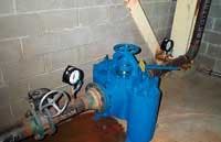
We encountered two problems during initial unit testing. First, on several occasions the mechanical strainer plugged with rust particles that broke loose from the very old makeup water supply line. A dual-compartment basket strainer was installed ahead of the unit to minimize or prevent future plugging issues (see Figure 5). The second problem that developed was a malfunction of the automatic controller on inlet valve V1. Vendor personnel promptly replaced the valve and controller, and the new equipment has operated error free since.
In early 2007, the hard drive on the lab computer that monitors the system failed. Plant technicians replaced it, at which point we discovered we had no backup disk of the operating and P&ID screens. The microfilter continued to operate via the main control system on the skid, but monitoring from the lab was impossible until we received replacement software. For those contemplating purchase of a microfilter or filters, make sure that a backup copy of all software is included with the system.
Conclusion
KPCL La Cygne power plant engineers calculate that payback for the microfilter will be less than three years from start-up date. As our budget permits, we hope to replace our Unit 2 clarifier and sand filters with two microfilters. This will provide redundancy. A thought is to design a system that has perhaps 20% excess capacity, such that all units can be routinely operated at less than maximum flow. Lower flow reduces fouling tendency of the membranes.
Of potential interest is that MF has the potential for pre-treatment of less-than-pristine source water for example, discharge from a sewage treatment plant as makeup. Systems utilizing difficult sources of raw water are typically set up for what’s known as Enhanced Flux Maintenance (EFM). EFM utilizes an additional, small skid that periodically subjects the membranes to short-duration chemical washes to remove accumulated solids, including organic materials. EFM may be critical where operator attention is sporadic.
About the Author: Brad Buecker is the air quality control specialist and former plant chemist at Kansas City Power & Light Co.’s La Cygne, KS, power station. He has previous experience as a chemical cleaning services engineer, water and wastewater system supervisor, and consulting chemist for an engineering firm. He also served as an engineer and analytical chemist for City Water, Light & Power, of Springfield, IL. Buecker has written over 70 articles and columns on steam generation, water treatment, and FGD chemistry, and he’s author of three books on steam generation topics published by PennWell Publishing. He is a member of ACS, AIChE, ASME, and NACE. Contact: [email protected]


