Membrane Cleaning Fundamentals: Cleaning Criteria and Normalization of Reverse Osmosis Systems
This series of five articles will discuss the cleaning of reverse osmosis systems. This first article describes cleaning fundamentals and subsequent articles will discuss cleaning skid design and cleaning procedures.
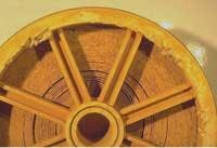
Iron fouled feed side of an element with telescoping damage and signs of mechanical force
Reverse osmosis (RO) systems have become the industry standard for purification of any feed water source - as well as wastewater and reuse applications, including a number of industrial processes. The typical lifetime of an RO membrane element is three to seven years depending on the application. In some RO systems, however, the membrane elements may only last one to two years.
The lifetime of RO elements is dependent on several factors, including system design, element selection, pretreatment, system operation, membrane cleaning, and system maintenance. This article and the subsequent articles will focus on the cleaning of RO systems containing spiral wound thin film composite membrane elements.
The surface of an RO membrane is subject to fouling by foreign materials present in the feed water, such as hydrates of metal oxides, calcium precipitates, organic and biological matter. The term “fouling” includes the build-up of all kinds of layers on the membrane surface, including scaling and biofilm buildup, for example.
Pretreatment Indicators
Most RO systems use pretreatment to minimize the performance decline of the membrane elements due to fouling and chemical attack. The type of pretreatment is dependent on the composition of the feed water source. For instance, surface waters typically have high concentrations of colloids (reflected as high turbidity levels and/or high SDI levels - SDI meaning silt density index). Most RO elements require turbidity levels less than 1 nephelometric turbidity units (NTU) and/or less than 5 SDI units. Multimedia filtration, microfiltration and ultrafiltration are unit operations commonly applied to reduce the colloids in the raw feed water.
The raw water source is often an indication for the type of fouling that can be expected in the membrane elements. For instance, in the case of surface waters, colloidal fouling, biofouling and organic fouling are often found on the membrane surface. Well waters typically have a potential for iron oxide or iron hydroxide fouling.
RO elements are supplied in different sizes. The most common sizes are 2.5”, 4”, and 8” diameter. RO systems containing 2.5” and/or 4” diameter membrane elements are seldom equipped with a cleaning skid. These membrane elements are either replaced or sent to a location where they can be cleaned. A few membrane chemical suppliers and original equipment manufacturers (OEMs) offer an off-site membrane cleaning service. In some cases, it’s cheaper to install new membrane elements than going through the trouble of cleaning the membrane elements. In the case of 8” diameter RO elements, cleaning is standard practice.
Many RO systems are equipped with a cleaning skid also known as a clean-in-place (CIP) skid which typically consists of a cleaning tank and a cleaning pump. The design of the CIP skid is very critical to achieve optimum cleaning results. Article two of this series, “Membrane Cleaning Fundamentals - CIP Skid Design and Operation,” will discuss the design of the CIP skid in detail.
For properly designed and operated pretreatment and RO systems, the typical cleaning frequencies are two to four cleanings per year for surface water, and one to two cleanings per year for well water.
Cleaning Frequency
Membrane manufacturers recommend cleaning when:
• Normalized permeate flow drops 10%.
• Normalized salt passage increases 5-10%.
• Normalized pressure drop increases 10-15%.
Effective or successful cleaning is dependent on the following factors:
• A cleaning is required when one of the key cleaning criteria above is met.
• A correctly designed cleaning skid is used.
• Membrane elements can withstand acid cleanings at pH 1 and alkaline cleanings at a minimum pH of 12. (Article three of this series will discuss the importance of pH for foulant removal.)
The reference point for the above key criteria is the stabilized performance of the RO system established during the first 48 to 72 hours of operation. If one of the above three cleaning criteria is met, then cleaning is recommended. If one waits too long (e.g., normalized permeate flow has dropped 30%) to clean, then it will become very difficult to effectively clean the membrane elements by standard cleanings - and may necessitate repeated cleanings or extreme cleaning.
Instead of applying the 15% normalized pressure drop increase as a cleaning criterion, some OEMs and end-users are applying 15 psi (1 bar) per element or 50 psi (3.4 bar) for a multi-element pressure vessel. This should be avoided for the following reasons. A typical normalized pressure drop for a multi-element vessel is approximately 15 psi. The 50 psi pressure drop cleaning criteria would mean that the pressure drop has increased 333%. Operating at 50 psi pressure drop may cause irreversible protrusion of the membrane element scroll commonly referred to as telescoping. In addition, membrane intrusion can result when excessive operating pressure pushes the membrane into the permeate channel spacer resulting in low permeate flow and high salt passage over time.
In addition, high pressure drops typically indicate severe fouling. Cleaning or repeated cleanings are often not able to restore the membrane element performance decline caused by the fouling. In addition, cleaning won’t restore the performance decline caused by the mechanical damage.
Importance of Normalization
The performance of an RO system is determined by different factors like the feed water composition, feed pressure, temperature and recovery. For example, a feed temperature drop of 4°C [7.2°F] will cause a permeate flow decrease of about 10%. This, however, is a normal phenomenon. To distinguish between such normal phenomena and performance changes due to fouling or other problems, the measured permeate flow and salt passage have to be normalized. Normalization is a comparison of the actual performance to a given reference performance while the influences of operating parameters are taken into account. The reference performance is typically the stabilized performance of the RO system within the first 48-72 hours of operation.
Most membrane manufacturers and a few OEMs have developed software programs to normalize operating data. The normalizing software programs offered by membrane manufacturers can be downloaded or requested through their web sites.
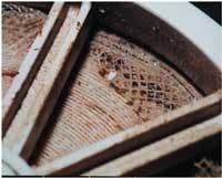
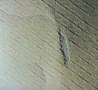
Scaled membrane surface with imprints from the feed spacer
Instead of using software programs to normalize, the normalized permeate flow, normalized rejection and pressure drop can also be calculated by hand by using ASTM standard D4516-00 (see: www.astm.org/database.cart/pages/d4516.htm). But this is cumbersome and labor intensive. Normalization software is commonly used and recommended.
Normalization is important to assess the performance of an RO system. It requires at least once daily collection of system parameters, such as pressures, flows, temperature, conductivity etc. The data are entered into the normalization software. Normalization is not only important to determine when cleaning is needed but it also shows the behavior of the membrane system. For instance, is the performance decline gradual or very sudden?
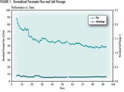
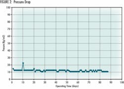
Figures 1 and 2 show the normalized performance of a certain site based on the utilization of the FT Norm software from The Dow Chemical Company (see: www.dow.com/liquidseps/design/ft_norm.htm).
In this specific case, the normalized salt passage and the pressure drop did not show significant increase. The main symptom of this plant is a permeate flow decline. The data indicate that the normalized permeate flow has declined steadily. The RO system seems to be fouled (assuming all process equipment is calibrated).
This system would have required cleaning on day seven, according to the cleaning criteria. Instead, the operation of the RO system continued without cleaning. As a result, the permeate flow of the system had declined 45% after 93 days of operation. With this much flow loss, routine cleaning may not be effective in restoring the membrane performance especially in cases of organic fouling, biofouling, colloidal fouling, sulfate scaling and calcium fluoride scaling. In these cases, extreme cleanings will be necessary.
Extreme cleaning is cleaning at pH and temperature conditions that are outside the guidelines of the membrane manufacturer and/or eventually combined with cleaning chemicals, such as bleach and ammonium bifluoride, that are not compatible with the membrane elements. These extreme cleanings may be able to restore the membrane performance to an acceptable level, but often the salt passage will be higher due to the harsh treatment. Applying an extreme cleaning is worthwhile, as it may delay membrane replacement.
Conclusion
Normalization is recommended in order to monitor the performance of RO systems. Normalized data are critical in determining whether one of the key cleaning criteria is met. It is recommended to clean an RO system when any one of the key cleaning criteria is met. If cleaning is put off, then standard cleanings may be ineffective. This could lead to the need for extreme cleanings, which can cause damage to the membranes.
About the Author: Jantje Johnson is a senior development specialist at FilmTec Corp., a subsidiary of The Dow Chemical Company. With over 21 years in liquid separations, Johnson has extensive experience in membrane applications, trouble-shooting, cleaning, and system design. She holds a degree in chemical engineering from the H.T.S. Groningen, The Netherlands. Contact: jjjohnson2@dow.com.
