Treating FGD Wastewater: Phase 2 Clean Air Act Amendments Make It Hot Topic

Jan. 1, 2007
Flue gas desulfurization is a hot topic right now with new emissions standards from Phase 2 of the Clean Air Act amendments coming into effect.

by Brian Heimbigner

Flue gas desulfurization is a hot topic right now with new emissions standards from Phase 2 of the Clean Air Act amendments coming into effect. The standards call for further reduction of sulfur dioxide (SO2) emissions from coal-burning power plants. Earlier reductions were required about 15 years ago by Phase 1 of the Act. FGD systems use limestone-forced-oxidation (LSFO) scrubbers to convert SO2 in the flue gas to carbon dioxide. While this increases greenhouse gases released to the atmosphere, it removes the SO2 that causes acid rain.

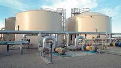
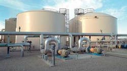
Tanks and pipes at power plant

Click here to enlarge image

With all the coal-fired power plants now in existence and the number of new plants in planning stages around the world, the market for FGD systems is growing rapidly. According to the McIlvaine Company, power plants will spend $168 billion for FGD systems between 2005 and 2020. Of the 2.2 million megawatts of coal-fired plants in operation in 2020, two-thirds will be equipped with FGD systems.

Scrubber Technology

FGD systems use either dry or wet scrubbers. Dry scrubbers use lime or limestone as a reagent to remove SO2; although they use water in the process, the water usage is lower than with wet scrubbers. When the power plant’s coal contains less than 2% sulfur, as it does in the U.S. West, the plant will typically consider using dry scrubbers. Wet scrubbers are preferred when the coal contains higher amounts of sulfur. These scrubbers use an absorber tower in which flue gas is contacted by the limestone slurry, resulting in conversion of SO2 in the flue gas into calcium sulfate (gypsum), with carbon dioxide (CO2) going up the stack. This article will focus on treating the purge stream from wet scrubbers.

The U.S. power industry alone produces over 120 million tons of coal utilization byproducts (CUBs) per year. CUBs consist of fly ash, boiler ash and FGD sludge. About 30% of CUBs produced by U.S. coal plants are used in commercial applications, reducing waste to be buried in landfills. For FGD sludge, these commercial applications include wallboard-grade gypsum and lesser quality gypsum used in the cement industry or for landfill stabilization.

To maintain required conditions in the scrubber, a constant purge stream is discharged from the scrubber system. The FGD purge stream contains pollutants from coal, limestone and make-up water. It’s acidic and supersaturated with gypsum, with high TDS, TSS, heavy metals, chlorides and dissolved organic compounds.

Treating the Purge

The scrubber purge stream is treated in a dedicated wastewater facility rather than any existing treatment system, for the following reasons:
  • The power plant’s existing wastewater treatment facility may not have adequate capacity.
  • The materials of construction of the treatment facility most likely are unsuitable for receiving a high chloride stream.
  • The treatment facility’s process design may not be appropriate for the very strict wastewater discharge limits likely to be enforced for the FGD wastewater.
  • FGD wastewater composition can vary significantly from plant to plant. The quantity and quality is affected by the rated capacity of the boiler, scrubber chloride concentration, efficiency of fly ash removal, type and efficiency of the dewatering system, type of FGD process used, and composition of coal, limestone and make-up water.

    Click here to enlarge image
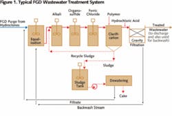
    A well-designed, integrated FGD wastewater treatment facility typically includes a number of technologies, such as lime neutralization, gypsum desaturation, heavy metal removal, clarification, filtration, biological treatment, and sludge thickening and dewatering.It’s important the vendor designing the treatment facility has full knowledge of FGD wastewaters and treatment experience to ensure the system will be properly integrated with the FGD scrubber operation. Key wastewater treatment design considerations are: process chemistry, solids handling and materials of construction.The treatment options for FGD purge are:
  • Dedicated physical-chemical treatment, consisting of precipitation, coagulation, clarification and filtration. This is the most common approach for FGD wastewater treatment. It lowers the potential for gypsum scaling and removes heavy metals and TSS to low levels. It requires specific reaction-train, clarifier, thickener and filter designs, with specialized materials of construction.
  • Evaporation and crystallization. While the advantages of this method include a small system footprint and a high quality distillate, it consumes a large amount of power and produces high amounts of solids that can be very difficult to dispose of if left in the calcium chloride (CaCl2) form. Capital costs can also be significant, as there’s a need for expensive high-alloy materials due to very high corrosion effects. There haven’t yet been any successful installations of this type in the United States.
  • Physical-Chemical Treatment ProcessesThe physical-chemical treatment process requires a number of steps: pH elevation/gypsum desaturation, heavy metal removal, coagulation and clarification.During pH elevation/gypsum desaturation, pH is raised to 8.5-9.2 using calcium hydroxide (Ca(OH)2) or sodium hydroxide (NaOH). Abundant metals, such as aluminum, iron and manganese form hydroxides, which represent a major solids load. Addition of lime or caustic also causes desaturation of gypsum in the stream. Seed sludge is recycled from the downstream clarifier to provide sites for gypsum crystal growth. This is a very important process, as it properly desaturates the stream and prevents scale from forming on the equipment.Although some heavy metals are removed as hydroxides, metal sulfides have much lower solubility. Therefore, in order to meet the low effluent requirements for heavy metals, organosulfides are dosed into the stream to precipitate the heavy metal sulfides.For coagulation, an iron salt such as ferric chloride is used in the next step of the treatment process. The iron salt helps denser flocs to form, thus enhancing clarifier performance. In addition, the iron salt may co-precipitate other metals and some organic matter.After the coagulation step, polymer is added to aid in solids formation. Next, the wastewater undergoes clarification using a reactor-clarifier design. After clarification, the pH is adjusted to neutral using hydrochloric acid (HCl). The flow may have to pass through a gravity filter if a low suspended solids level is required prior to discharge of the treated wastewater. In this case, the backwash water from the filter is returned to the front of the wastewater treatment system.The clarifier sludge contains gypsum, inert material, and precipitated metals, and is typically 8-10% solids by weight. It’s normally pumped to an agitated holding tank, sized to hold 12 to 24 hours of sludge production. It’s then dewatered with recessed chamber filter presses or belt presses, based on the volume of sludge to be dewatered.Depending on the discharge permit for the power plant, additional treatment may be required downstream of the physical-chemical treatment system. Some jurisdictions are requiring limits on organics, total nitrogen and selenium in the discharge stream. These constituents are removed using biological processes that add significantly to the complexity, footprint and capital cost of the plant.ConclusionProper treatment of the flue gas desulfurization purge stream is an essential part of the FGD system. Specific FGD experience is crucial for ensuring that the wastewater treatment plant is properly designed so that it will operate reliably and will consistently meet the plant’s discharge requirements. About the Author: Brian Heimbigner is power business development manager for Siemens Water Technologies. With a bachelor’s degree and MBA from the University of Washington and graduate studies at the University of Wisconsin, he has over 25 years of experience in industrial water and wastewater equipment and systems applications. Contact: 678-446-5273 or [email protected]

    Sponsored Recommendations

    NFPA 70B a Step-by-Step Guide to Compliance

    NFPA 70B: A Step-by-Step Guide to Compliance

    How digital twins drive more environmentally conscious medium- and low-voltage equipment design

    Medium- and low voltage equipment specifiers can adopt digital twin technology to adopt a circular economy approach for sustainable, low-carbon equipment design.

    MV equipment sustainability depends on environmentally conscious design values

    Medium- and low voltage equipment manufacturers can prepare for environmental regulations now by using innovative MV switchgear design that eliminates SF6 use.

    Social Distancing from your electrical equipment?

    Using digital tools and apps for nearby monitoring and control increases safety and reduces arc flash hazards since electrical equipment can be operated from a safer distance....