Membrane Technologies for Industrial Water Treatment

Sept. 1, 2006
In a Zenon Environmental presentation a few years ago, the words on a slide captured my attention...

In a Zenon Environmental presentation a few years ago, the words on a slide captured my attention as being both accurate in the moment and a predictor of the future. The words were: “Membranes are to water treatment what the microchip is to information technology.” The boom in membrane water treatment over the past few years, with relatively high growth rates in existing market segments and expansion into new market ones, I think, validates that prediction.

There are two general categories of membrane water treatment technologies. These are:
  • Pressure driven technologies
  • Electrical potential driven technologies
  • In Part 1 of this two-part series of articles, pressure driven membrane water treatment technologies were discussed. This article covers electrical potential driven membrane water treatment technologies. These technologies include:
  • Electrodialysis (ED)
  • Electrodialysis Reversal (EDR)
  • Electrodeionization (EDI)
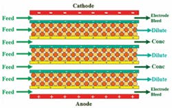
  • Electrical Potential Driven MembranesThese membranes are designed to allow passage of certain ions through a membrane but not allow passage of water molecules. Ions are classified as “cations” if they possess one or more positive charges and are classified as “anions” if they possess one or more negative charges.Membranes for electrical potential driven technologies are essentially made from ion exchange resins. Many readers will be familiar with ion exchange resin beads used in water softening, which commonly use strong acid cation resin. Undesirable scale-forming cations like calcium and magnesium are exchanged within the resin bed with non-scale-forming sodium ions. The resin in a water softener is called a cation exchange resin.In electrical potential driven water treatment technologies, cation exchange resin is cast onto a fabric or ground up within a plastic matrix to form what is called a cation exchange membrane. Only cations can pass through a cation exchange membrane. Negatively charged anions can’t pass through a cation exchange membrane due to repulsion by the negative charge of the resin.Strong base anion resin is made into anion exchange membrane. Only anions can pass through an anion exchange membrane. Cations can’t pass through due to the positive charge of the resin.ElectrodialysisElectrodialysis (ED) isn’t a common water treatment technology for drinking water or industrial process water. It’s only mentioned here so we can progress step by step from ED to EDI.In the electrical potential driven technologies, a direct current (DC) power supply is connected to two electrodes. The negative electrode is the cathode. The positive one is the anode. Alternating sheets of cation exchange membrane and anion exchange membrane are placed between the electrodes. Feed water is pumped into channels located between the membrane sheets. The cathode will attract positively charged feed water cations. The anode will attract negatively charged feed water anions.Channels enclosed by cation exchange membrane located on the same side as the cathode and anion exchange membrane located on the same side as the anode are called diluting channels, or dilute channels. This is because ions will leave the feed water and pass out of these channels.Channels enclosed by anion exchange membrane located on the same side as the cathode and cation exchange membrane located on the same side as the anode are called concentrating channels, or concentrate channels. This is because ions that pass from the feed water into these channels can’t leave these channels so these channels become concentrated with ions. The concentrate channels next to the electrodes are called the “electrode bleed channels”.

    Click here to enlarge image
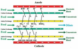
    Figure 1 illustrates how feed water enters the dilute channels, then feed water ions pass out of the dilute channels and into the concentrate channels through the appropriate membranes due to their attraction to the oppositely charged electrode.The result is a product water from the dilute channels and a waste stream from the concentrate channels. It’s common to recirculate a portion of the concentrate back to the concentrate channels and only send a relatively small amount of concentrate to drain.Electrodialysis ReversalIt was found that operating ED units on most brackish waters caused too much scaling in the concentrate channels. The requirement for chemical cleaning was too high. The solution was to reverse the polarity of the electrodes every few minutes and change the valving so that concentrate channels became dilute channels, and dilute channels became concentrate channels. This keeps electrodialysis reversal (EDR) units relatively clean.The difference between ED and EDR, therefore, is that in ED units the electrodes have fixed polarity, dilute channels are always dilute channels and concentrate channels are always concentrate channels. Figure 2 illustrates the process with the polarity of the electrodes reversed compared to Figure 1.

    Click here to enlarge image
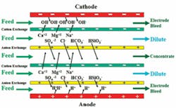
    EDR may be used for drinking water production from brackish well water sources and for some industrial processes. The largest EDR facility in the United States is a drinking water plant in Sarasota, FL.ElectrodeionizationElectrodeionization (EDI) is a high purity water treatment technology. It takes the place of a polishing mixed bed ion exchange unit in many applications. EDI units must have excellent quality feed water, usually reverse osmosis (RO) permeate.EDI units are similar to ED units but with strong acid cation and strong base anion resin beads either mixed together or layered in the dilute channels. Layering means a certain volume in each dilute channel is filled with only strong acid cation resin beads followed by a certain volume of strong base anion resin beads, and so on. Figure 3 illustrates flows and mixed resin beads in the dilute channels of an EDI unit.
    Click here to enlarge image
    Like ED, polarity of the electrodes doesn’t change in EDI units. Dilute channels are always dilute channels and concentrate channels are always concentrate channels.To reduce resistance across the EDI stack, a certain minimum conductivity is maintained in concentrate channels by injecting sodium chloride and/or by recirculating a portion of the concentrate or by filling the concentrate (and sometimes the electrode) channels with resin beads. Resin beads are more conductive than dilute solutions. The all-filled design where concentrate spacers are filled with resin beads is an Ionpure® CEDI patented feature registered to Siemens AG.The reason EDI technology is growing at such a rapid rate is because no chemical regeneration of ion exchange resins is required. With standard mixed bed polishing beds, strong acid cation resins must be regenerated with hydrochloric or sulfuric acid and strong base anion resins must be regenerated with sodium hydroxide.EDI resins are electrically regenerated. After most feed water ions have been removed, the electrical potential splits water molecules into hydrogen ions and hydroxide ions. This leaves beads in the downstream portion of the dilute channels in their regenerated form, allowing high purity water to be produced.ConclusionMembrane water treatment is growing at a fast pace. This includes pressure driven membranes as well as the electrical potential driven membranes, especially EDI. Membrane water treatment is booming. Water treatment professionals need to learn as much as possible about these membrane technologies. There’s a world of opportunity for those that have the knowledge, skills and abilities to provide the greatest service in any one or more areas of membrane water treatment, including design, installation, operation, maintenance and troubleshooting. About the Author: David Paul is president of David H. Paul Inc., an advanced water treatment training and multimedia production firm. He has over 27 years of advanced water treatment experience as an operator, manager, instructor and consultant. Contact: [email protected] or www.dhptraining.com

    Sponsored Recommendations

    NFPA 70B a Step-by-Step Guide to Compliance

    NFPA 70B: A Step-by-Step Guide to Compliance

    How digital twins drive more environmentally conscious medium- and low-voltage equipment design

    Medium- and low voltage equipment specifiers can adopt digital twin technology to adopt a circular economy approach for sustainable, low-carbon equipment design.

    MV equipment sustainability depends on environmentally conscious design values

    Medium- and low voltage equipment manufacturers can prepare for environmental regulations now by using innovative MV switchgear design that eliminates SF6 use.

    Social Distancing from your electrical equipment?

    Using digital tools and apps for nearby monitoring and control increases safety and reduces arc flash hazards since electrical equipment can be operated from a safer distance....