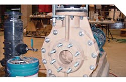
Usually, water pumps show satisfactory vibration levels during the test runs at the manufacturer’s shop. However, the vibration levels after the commissioning at the site could be higher than the desirable level. Too often, after several months of operation, the vibration could show some increasing trends. This is the usual story of many medium and large water pumps (above 400 m3/h and 1,800 gpm).
The initial steps to diagnose the high vibration problems for a water pump are:
- The unbalance should be checked
- The alignment should be checked
- The vibration analysis should be carefully checked and verified by proper vibration tests/measurements.
This article will also discuss practical notes on modern vibrational condition monitoring techniques to identify unbalance, misalignment and excessive radial loads.
The bearing, rotordynamics study and vibration monitoring
The importance of proper bearing type/design should always be insisted. The tilting-pad bearings are appreciated for any high-speed and large water pump. In addition to very high stability offered, the preload capability inherent in the tilting-pad bearing design (and the offset pivots) can result in the satisfactory oil-film stiffness and damping.
For a successful rotordynamics study, the entire water pump train should be analyzed and all the supports and bearings should be properly introduced into the dynamic model. From the theoretical point of view, the water pump system is usually an indeterminate system, in which the flexibility of the bearings/supports and the flexibility of the shafts, determines the load distributions. In other words, loads could be the function of the bearing/support stiffness, which could vary with the pump speed and many other operational parameters.
Another important aspect is the “anisotropy” in the water pump rotordynamics behavior. As a result of the anisotropy, there are coupled “pairs” of natural frequencies, for vertical and horizontal directions (closely related vertical and horizontal natural frequencies). For example, in a water pump, because of anisotropic effects, a pair of first natural frequency, “1.02×f1” for the first vertical natural frequency and “0.98×f1” for the first horizontal natural frequency, is obtained instead of the first natural frequency “f1” calculated by the isotropic assumptions. The anisotropy could affect the second natural frequency even more. In the above mentioned example, a pair of closely related frequency, “1.04×f2” for the second vertical natural frequency and “0.96×f2” for the second horizontal natural frequency, is obtained (the second natural frequency “f2” calculated by the isotropic assumptions).
High vibrations in a water pump could be caused by the balance shift because of the rotating component fits, such as impellers, blade assemblies, others, any unbalance, improper installation of coupling(s), misalignment, poor foundation, hydrodynamic related instabilities, light rubs, seal rubs, the poor lubrication of the bearings and so forth. These malfunctions could affect the vibration of the water pumps. The vibration monitoring is important in determining the condition of water pumps.
Unbalance
The unbalance is the most common malfunction in a water pump. In an unbalanced condition, the water pump rotor mass centerline does not coincide with the axis of rotation (condition of unequal mass distribution at each section of the pump rotating assembly). The unbalance represents the first, fundamental mechanism to transfer the rotational energy into the vibration. The rotor response depends on both the rotor combined dynamic stiffness (combined effects of stiffness, damping and other dynamic effects) and the unbalance excitation. Any change in the rotor response may result from either a change in the unbalance or a change in the restraining rotordynamics stiffness components — for example, a crack in a water pump shaft would reduce the rotor stiffness.
The synchronous vibration responses, provided by lateral displacement transducer(s) during a water pump rotor operation, start up or shutdown, are usually presented in the “Bode” plot (the “vibration amplitude vs. rotating speed” and the “phase lag vs. rotating speed”) and “Polar” plot formats. These formats are widely used for the unbalance and other problem diagnosis (and corrections).
The damped unbalance dynamic response test, known as “synchronous test,” consists of inputting a controlled unbalance to the rotor and measuring its synchronous response. It is a very important dynamic test.
Coupling angular stiffness
The importance of coupling angular stiffness is usually overlooked for water pump rotordynamics and water pump dynamic/vibration studies. The angular stiffness of some couplings — for instance, some metal disk couplings — could be extremely high. This angular stiffness should be properly modeled in the pump rotordynamics, otherwise this can make the rotordynamics results invalid. Sometimes, to achieve a satisfactory rotor response and a suitable dynamic behavior, an angular stiffness limit should be specified for the coupling. In some other cases, a coupling should be changed in an existing water pump to achieve a suitable coupling angular stiffness and an acceptable dynamic behavior. The issue of high angular stiffness could cause more problems on the overhung-style water pumps. Usually, a coupling with lower angular stiffness can result in a better mechanical/dynamic separation of different rotors in a water pump train.
Alignment
Following the unbalance, the misalignment of water pump train rotors is the second most common reason for the water pump high vibration events. There is always concern that a misalignment (or an alignment deterioration during operation) with a coupling that has a high angular stiffness could lead to a high loadings on the water pump bearing(s). Nowadays, the laseroptic methods are considered routine.
In addition of high loads on the bearings, the misalignment can cause a radial force, which pushes the rotor to the side. The same result could occur by a strong radial component of a water flow in a water pump. The gyroscopic effect (a speed dependent component), the gravitational load on horizontal rotors, thermal expansion load, offset, cocked bearing-related load and gear mesh forces can also affect the rotor loadings.
Because of the radial forces, the water pump rotor becomes displaced from the original position and moved to higher eccentricity ranges. It may also become bowed and rotate in a bow configuration. In these conditions, the nonlinear effects of the system become active. Because of the nonlinearity, the forced response of the rotor generally contains the synchronous component, and its higher harmonics (2, 3, 4, etc). The harmonics (particularly 2×), abnormal orbital motion, abnormal radial average shaft centerline position and abnormal shaft versus casing motion are indicative of an excessive misalignment or a high radial load.
In a misalignment situation (or as result of an increasing radial load), the elliptical nature of the rotor center orbit transferred to the “Banana” shape because of the nonlinear effects. In other words, as the orbit changes from an elliptical shape to a “Banana” shape, it can be an indication that higher frequency components are present. Axial vibrations of the water pump rotor could additionally indicate an impending excessive radial load or a misalignment problem in a water pump.
A continuously-acting radial load — as result of a misalignment or an excessive pump/water radial load — on a rotor can cause reversal stresses in the rotor fibers. For a high-speed continuously operating water pump, the number of the stress reversal cycles could swiftly reach the fatigue limit, which can lead to a rotor cracking and a rotor premature failure.
Case study
The case study is about a high vibration incident in an overhung-impeller water pump. After one month of operation, it was reported that the vibration amplitude of the shaft, particularly on the inboard bearing (the bearing near the coupling) approached to a trip set point. The water pump had tripped because of the high vibrations. Inspections after the trip showed some seal and vibration damages.
The main reason of the failure was an improper coupling. A high angular stiffness coupling (a metal disk coupling) was used that resulted in a very high loading on the bearing and seal combined with a misalignment, which caused damages to these sensitive components. To solve the issue, the following corrective actions were taken simultaneously:
- A suitable coupling with a lower angular stiffness was selected (a sophisticated diaphragm-type coupling).
- A rotordynamics analysis, considering the coupling effects, was performed. This study confirmed the suitability of a new coupling and predicted low vibrations.
- A proper alignment limit is specified and controlled.
By these modifications, the water pump showed a satisfactory operation and a low operating vibration.


