During much of the last century, many central power stations came on-line to satisfy the rapidly growing need for electricity in the post-WWII United States. Large power stations were a wonder of technology at the time, and I began my career at one of these plants in the early 1980s. However, even as people marveled at these facilities and their intricacies, it came to be recognized that the net thermodynamic efficiencies of these plants were low, with a mid-30 percent range for subcritical drum units, and at most mid-40 percent for even advanced supercritical units.
The primary factor for the relatively low efficiencies is that much of the latent heat transferred to water in the boiler is lost during condensation of the turbine exhaust steam for condensate return to the boiler.1 Thus, for all conventional power units, well over half of the fuel energy was, or in the case of remaining units, is unavailable. Furthermore, most of these large boilers were fired by coal, which produces much carbon dioxide.
Toward the end of the last century and through the first two decades of this century, a significant conversion has come to combined cycle power generation, wherein a combustion turbine or turbines produce a large portion of the power (the Brayton thermodynamic cycle), with the turbine exhaust heat utilized to generate steam and additional power via the standard Rankine thermodynamic cycle. Modern combined cycle units have net efficiencies approaching or exceeding 60 percent. This efficiency, coupled with natural gas as the typical fuel, ensures such plants produce much less CO2 than coal-fired boilers.
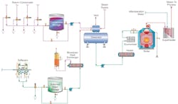
However, as resource conservation and concerns regarding global climate change continue to grow, so does development of cogeneration and combined heat and power (CHP) facilities. Steam is typically utilized for multiple purposes at these plants, including power production, energy for process heat exchangers, power to drive turbines that operate heavy machinery, and in the case of CHP, heat and chilling for central business districts in large cities and for hospitals, universities, and other institutions. A general outline of a steam generating system at an industrial cogeneration facility is shown in Figure 1.
For cogenerating plants, the steam turbines are often of the non-condensing style, in which only a portion of the steam’s energy is utilized for turbine work, and the steam is extracted while still in superheated condition for other uses. Because most of the process steam is used for direct heating, the latent heat is recovered rather than wasted. Thus, overall net efficiencies at some cogeneration plants may reach 80 percent. Such energy efficiencies are impossible to ignore and are a prime reason why the technology continues to grow in popularity.
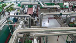
However, in addition to the steam generation system proper, cogen and CHP facilities often have miles of steam and condensate return piping, plus dozens or perhaps even hundreds of heat exchangers throughout the campus. The metallurgy of this equipment can be quite variable and may include carbon steel condensate piping and boiler components, copper-alloy or stainless-steel heat exchangers, and perhaps even exotic alloys for special heat exchange applications. The complexity of such systems makes many components susceptible to deposition, corrosion, and fouling. Many in the industry have been working diligently to improve solutions to these issues, and the next sections examine modern treatment methods for some of the major equipment and systems shown in Figure 1.
Makeup Water Treatment
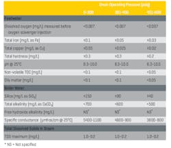
Table 1 outlines long-standing chemistry parameters for low-pressure boiler water chemistry in low- to medium-pressure water-tube industrial boilers.
Table 1. Guidelines for impurity limits in low-pressure industrial boilers
A particular highlight from the data above is the recommended low concentrations of total feedwater hardness. The reaction below is by far the most common scale-forming mechanism that occurs in untreated or poorly treated boiler makeup water.
Ca2+ + 2HCO3- + heat → CaCO3↓ + CO2 + H2O
The equation outlines the inversely soluble reaction (a function of temperature) of calcium ions (Ca2+) and bicarbonate alkalinity (HCO3-) to form calcium carbonate (CaCO3), which often plagues hot water systems and boilers.
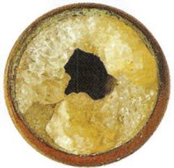
Accordingly, sodium softening is the common core boiler makeup treatment method for low-pressure steam generation makeup water treatment at many existing facilities, often with no additional treatment. This straightforward technology minimizes calcium carbonate deposition by reducing hardness. However, several serious concerns arise with sodium softening as a stand-alone treatment method. For starters, I regularly see reports from colleagues who are visiting facilities for the first time and find that the low-pressure steam generators are heavily fouled with hardness deposits (see Fig. 2).
This is part of a pattern (which I have observed from my own direct experiences) where at many facilities the water/steam plants are more or less neglected in attention and funding, with most of the focus being on process chemistry and engineering. Yet, water/steam system failures can cause at least partial unit shutdown and, in some cases, threaten employee safety.
Secondly, even though Table 1 indicates that a significant amount of bicarbonate alkalinity (HCO3-) can be tolerated in low-pressure boilers, the alkalinity, upon reaching the boiler, is in large measure converted to CO2 via the following reactions:
2HCO3- + heat → CO32- + CO2↑ + H2O
CO32- + heat → CO2↑ + OH-
CO2 flashes off with the steam and can increase the acidity of the condensate return when the CO2 redissolves in the condensate.
CO2 + H2O ⇔ H2CO3 ⇔ H+ + HCO3-
Although the pH generated by this reaction has a relatively mild lower limit, the acidity is more than enough to cause significant carbon steel corrosion in condensate return systems.
Makeup water production technology, like many others, has evolved significantly in the last several decades, and a number of solutions are available to improve boiler feed quality. A technique that has become quite common for the power industry (as the first of two steps in makeup demineralization), and is increasing in popularity for other industries, is reverse osmosis (RO), which can remove 99 percent or greater of all dissolved ions from makeup water. RO systems can be very reliable with proper pretreatment, although careful planning is required when replacing merely softened water with the more “hungry for ions” RO permeate.
Boiler Feedwater (and Condensate Return)
Operating in a mildly basic pH range is critical for minimizing general corrosion in boiler feedwater and (normally) condensate return. Table 1 suggests a range of 8.3–10.0, but if copper alloys are not present in the systems, the lower limit can be raised, preferably to at least 9.0. In the power industry, the common feedwater pH-conditioning chemical is ammonia, which elevates pH via the following reaction:
NH3 + H2O ⇔ NH4+ + OH-
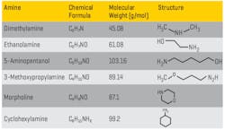
As evident from the equation, this is an equilibrium reaction, so the pH increase is limited, which usually minimizes excessive steel corrosion in the event of a chemical feed upset. (Copper alloy corrosion is a completely different story.) But ammonia is very volatile, and the compound significantly partitions with steam in low-pressure boilers. For industrial units, neutralizing amines are a common alternative for feedwater pH conditioning (see Table 2). These are small-chain organic molecules with an ammonia group attached to or embedded within the compound.
Table 2. Common Neutralizing Amines
Developing the best program has sometimes been difficult with these compounds, as each has a different basicity and distribution ratio (the tendency for the product to depart with steam or remain dissolved in the boiler water). In many complex industrial steam generation/condensate return systems, it is desirable to have proper pH control throughout the network, but a single compound may not be sufficient to achieve this control. Blended amine products have been developed that can provide wide-ranging coverage. A thorough analysis of system design, metallurgy, current chemistry and operating temperatures is a prerequisite for proper program selection.
Recent years have seen a re-emergence of film-forming substances for corrosion protection. The idea of utilizing film-forming chemistry for steam generating system protection is not new, as decades ago film-forming amines (FFA) were introduced by the water treatment industry, with a common compound being octadecylamine (C18H39N). The amine group on each molecule attaches to the metal substrate, and the long-chain organic compound extends into the water and acts as a barrier. However, poor control and lack of detailed knowledge of the overall chemistry often led to problems, including formation of “gunk balls” in the common vernacular, which fouled steam generators.
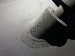
Advancements in chemical synthesis techniques and analytical instrumentation have led to the development of new film-forming substances that are much more effective at protecting metal surfaces. This includes the FFA products of ChemTreat’s TITAN360™ series. Figure 3 shows a protected metal surface (during off-line conditions). Note how the water beads rather than wetting the surface.
When correctly applied, film-formers can be quite protective of metal surfaces during normal operation and unit downtimes. In a recent application at a combined cycle plant in the Northeast, the TITAN360 product brought feedwater iron concentrations down to a low part-per-billion (ppb) level, where they remained during frequent load swings.
It must be noted that implementing FFA programs, as with any others, requires proper system oversight and control. Well known are examples where a less-than-knowledgeable vendor suggested that such chemicals could be injected into the unit and all corrosion issues would magically disappear. Severe problems were the result instead. A careful analysis of system operation and past/present chemistry is necessary beforehand, with careful monitoring and control still required after FFA chemistry is implemented. This chemistry is strongly influenced by pH, which must be diligently monitored and adjusted with neutralizing amines to maintain proper FFA performance.
Beyond these issues lies the potential for severe impurity ingress to steam generators via contaminated condensate return. I once inspected the steam system at an organic chemicals plant in which the superheaters of four 550-psig package boilers had to be replaced every one and a half to two years because of excessive deposition and overheating. A review of water chemistry data provided by an outside vendor showed total organic carbon (TOC) concentrations in the condensate return as high as 200 mg/L. Contrast this value with the 0.05 mg/L feedwater limit recommended in Table 1. The high organics caused severe foaming in the boiler drums and carryover of impurities to the steam.
Figure 1 illustrates automatic dump valves on the condensate return lines, where it is common to dump condensate based on specific conductivity measurements. An important point to note is that frequent condensate dumping caused by process fluid leaks can enormously increase the amount of makeup needed for the steam generators. In some cases, it might be more cost effective to install condensate polishers on the return lines to remove impurities and save the condensate. Again, a thorough analysis of system design and operation is necessary to make this determination.
Other Issues
Space limitations prevent further detailed discussion of other components and processes within the system outlined in Figure 1, but a few important points should be highlighted. One is dissolved oxygen (DO) control in the boiler feed. This has been a thorny issue in the power industry, where complete DO removal has caused flow-accelerated corrosion (FAC) problems.3 While FAC can potentially be an issue at cogen plants, it is important to prevent excessive oxygen ingress, which can cause severe pitting in feedwater lines and economizers. A mechanical deaerator is the industry-standard solution, as shown in the figure. Normally, chemical treatment is utilized for supplemental DO control.
Secondly, the wide variability between process conditions, boiler designs, and steam needs within and among plants requires flexibility in direct boiler water treatment methods. Programs are normally designed to control one or more of several factors, including pH, hardness ingress, and iron oxide deposition. Treatment options include standard phosphate feed, chelants, and a variety of polymers to sequester certain ions or compounds. Often, a combination of two or more products may be the most effective. Again, as has been emphasized for other programs, the choice of a boiler water treatment program should be carefully evaluated based on process chemistry and operational issues. Some products may do more harm than good if misapplied. WT
References
1. B. Buecker, “Steam Generation Thermodynamics”; Chemical Engineering, November 2010.
2. Consensus on Operating Practices for the Control of Feedwater and Boiler Water Chemistry in Modern Industrial Boilers, The American Society of Mechanical Engineers, New York, NY, 1994.
3. Guidelines for Control of Flow-Accelerated Corrosion in Fossil and Combined Cycle Plants, EPRI Document 3002011569, the Electric Power Research Institute, Palo Alto, CA, 2017.
