Multi-variable output pressure instrumentation increases process efficiencies for water applications
by Karmjit Sidhu
Multi-variable sensors (with more than one output) offering pressure + temperature, upstream pressure (P) + differential pressure (dP), and upstream liquid or gas temperature + differential pressure offer multiple benefits over the use of two traditional discrete devices. The main benefit is the reduction in process penetration points, leading to less mechanical leak points for the process liquid or gas. Other benefits include reduced component costs, less wiring costs and easier installation.
The multi-variable version of the upstream pressure + differential pressure sensor reduces process penetrations from three to two and component count from two to one, making it ideal for pump and filter condition monitoring in water booster systems and pumping applications.
As the demand for water pumping applications grows around the globe, the need for efficiencies and savings are forcing OEMs to look at automation of booster and packaged systems. In water pumping, there are three main areas of focus: constant flow, constant pressure and variable flow.
The increased use of variable frequency drive (VFD) technology to electronically vary the speed of an electric motor over older mechanical technologies is creating new opportunities for electronic pressure sensing in closed-loop systems. Pressure transducers are used in place of pressure or flow switches to provide precision closed-loop system stability and reliability. For larger systems, a pressure-based flow measuring meter can be used to maintain pressure with regulated flow as a cost-competitive solution when using a multi-variable pressure measuring device.
Pressure-Based Meters
Many pressure-based meters can be used with a differential pressure transducer to provide linear and stable electronic measurements. Electronic outputs in the form of 4-20 mA or frequency can be read by a programmable logic controller (PLC) to enhance system capability and reliability with full diagnostics. The principle behind this technique is called the Bernoulli's Principle for fluid flow to determine the flow rate. Some of the most common and widely used pressure-based meters are:
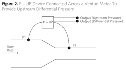
- Venturi meter -- A device that measures the pressure reduction of fluid pressure that results when a fluid flows through a constricted section of pipe. As fluid flows through a venturi, the expansion and compression of the fluids cause the pressure inside the venturi to change, which is measured with a differential pressure transducer. Fig. 1 shows a P + dP device connected across a venturi tube to measure upstream (P1) and differential pressure (P1 - P2) from one measuring device. This configuration allows the fluid pressure and flow to be controlled with reduced process penetration points in the system. A venturi meter is more accurate and costly in comparison to an orifice plate.
- Orifice plate -- a device consisting of a thin plate with a hole in the middle. It is usually placed in a pipe in which fluid flows. When the fluid reaches the orifice plate, the fluid is forced to converge through the small hole; the point of maximum convergence actually occurs shortly downstream of the physical orifice. Volumetric or mass flow rate may be determined, depending on the calculation associated with the orifice plate. It uses the same principle as a venturi meter. A connection system can be applied here to provide desired outputs (see Fig. 1). It is typically less accurate than a venturi meter but could cost as much as 30 percent less.
P + dP transducer concepts
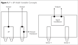
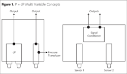
The market features two types of devices offering the P + dP concept. One uses a true dP transducer in conjunction with a stand-alone pressure transducer to provide the two outputs. This is an accurate but costly solution since stainless steel dPs are traditionally expensive and bulky. The other solution is to use two calibrated pressure transducers with a high level output such as 1-5v and use a processor to take the difference between the two transducers to provide the dP output signal. Alternatively, one can also use a low level signal, such as a millivolt output, and do the summation using a special signal processor. Fig. 2 shows the two concepts of the P + dP transducer.
The two sensor dP concept, as shown on the right hand side of Fig. 2, offers a lower cost and compact size; however, it has some drawbacks using traditional sensing technologies, such as bonded metal foil strain gages, metal thin film, printed thick film, and ion implanted silicon strain gages. Due to their low output signals (2mV/V in case of metal foil and thin film gages, 4mV/V for thick film, and 20mV/V for ion implanted), users cannot get low dP ranges needed in high line pressures.
When measuring flow rates using venturi or orifice plates to maintain a maximum flow rate with reduced losses in line pressure, the dP range needs to be between 10 psi and 20 psi with line pressure of 90 to 300 psi. To maintain accuracy within 2 percent of full scale over pressure and operating temperature, most of the technologies previously mentioned are not able to deliver the 10:1 to 15:1 turn down ratio (typical values for booster systems) needed to maintain accuracy.
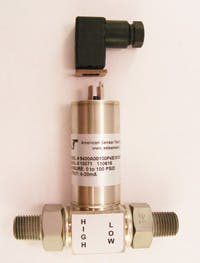
Recent developments in sensor technologies -- such as Krystal Bond™ Technology by AST Sensors (www.astsensors.com) that use bulk silicon strain gages employing Micro Electro Mechanical Systems (MEMs) with high output signal (raw signal 50mV/V) and multi channel Application Specific Integrated Circuits (ASIC) -- are offering a high turn down ratio such as 15:1. In a typical chilled water pumping application, it is now possible to measure 20 psi dP in 300 psi line pressures. Fig. 1 shows a P + dP transducer with MEMs technology. This transducer also offers temperature (T) + dP as an alternative transducer, if needed.
Summary
MEMs-based multi-variable pressure transducers with P + dP outputs offer OEMs with water pumping applications a reduced cost solution to the traditionally expensive, true dP + P solution. To maintain better system accuracy, this can be further expanded to offer P + T + dP from a single device.
About the author: Karmjit S. Sihdu is Vice President of Business Development and co-founder of American Sensor Technologies Inc. He has over 25 years experience in pressure and position sensing sales and engineering. Sidhu is currently completing his PhD in Material Science. He can be reached at: [email protected].


