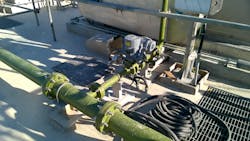
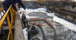
Piping is an important part of modern water and wastewater treatment systems, water pumping units, desalination units, cooling water systems and others. Piping systems are like veins of modern plants. The piping is used to carry water, wastewater, chemicals and mixtures from one location to another. The design, construction, operation and maintenance of various piping systems involve an understanding of piping fundamentals, materials, generic and specific considerations, fabrication and installation, examinations, and testing and inspection requirements, in addition to the local and international regulations. Piping requires the application of theory from a number of engineering disciplines, including fluid mechanics, statics, dynamics, strength of materials, and metallurgy.
This article identifies and explores the various facets of piping in water and wastewater treatment plants and water-related facilities. It highlights some important aspects and parameters that should be considered in the process of piping design, engineering, installation and operation.
Pressure drop through piping
Pressure drop or head loss occurs in all piping systems because of friction within the pipe and fittings and elevation changes. There are pressure drops because of turbulence caused by abrupt changes in direction, which is usually included in the overall frictional pressure drop. Although there is software to accurately calculate pressure drops, many engineers like to use simple rules of thumb to estimate pressure drops in preliminary/basic designs, without complex formulations or complicated software, tables or procedures.
As a very rough indication, for 10 m of water piping with velocity around 1 m/s, an estimate on frictional pressure drop would be around 0.1 m of head (or say, 1 m frictional head for 100 m of pipe). This is a very rough indication for a 4- to 8-inch diameter pipe (DN100-200mm). For small diameter pipes, more pressure drop could be expected. For large diameter pipes, pressure drop could be less.
As another rough indication, based on simplified equations, the following formula can be used for the first guess:
pressure drop ~ L V2 / D
where: L is the length of the pipe, D is the hydraulic diameter of the pipe, and V is the average velocity of the fluid flow (equal to the volumetric flow rate per unit cross-sectional wetted area).
Typically, the velocity is relatively low in low-pressure piping and relatively high in high-pressure piping. Low velocities, somewhere between 0.6 m/s and 1.4 m/s is preferred for suction piping (suction of pumps), intake and gravity flow lines. However, for other piping (piping at discharge, etc.), a velocity between 2 m/s and 4 m/s might be used. Some standards and specifications have extended the upper velocity limit to 5.5 m/s. Since velocity is related to flow rate and pipe diameter, pressure drop depends strongly to the pipe diameter. For a piping of circular section, just for rough estimation:
pressure drop ~ L Q2 / D5
where Q is the volumetric flow rate.
Head loss in fittings is frequently expressed as the equivalent length of pipe that is added to the straight run of pipe. In theory, using this method, the pressure drop through the fitting or a valve is equivalent to the pressure lost through a certain length of pipe at that corresponding flow rate. This approach is just a rough approximation, and it does not usually consider turbulence and other complicated effects. However, this is usually acceptable as an estimate.
As rough indications, equivalent pipe length for reducers and elbows might be a value between 3 m to 9 m. Similar values might be considered for the entrance such as an entrance of a tank or vessel (drum, filter, etc.). For a “tee,” equivalent pipe lengths are usually higher, say, a value between 9 m and 15 m. For valves, equivalent pipe lengths are typically high and they often vary, for example, 10 m to 60 m. They depend on the type and details of the valve.
The equivalent pipe length of well-designed simple gate valves or ball valves (fully open) are usually less than complex glove valves used for the flow control. For instance, for gate valves, ball valves or other valves with less frictional effects on water flow, the equivalent pipe lengths could be around or below 15 m. For globe valves and other complex/control valves with more frictional effects, equivalent pipe lengths might be above 35 m. Partially open valves impose high pressure drop and frictional losses are far more than the above values. All these are typically for 4- to 8-inch diameter pipe (DN100-200mm).
Considering the idea of “linear” variation, some experts have suggested equivalent pipe length as a factor to diameter, known as L/D ratio method. This equivalent length method (L/D ratio) describes the pressure drop through a fitting or valve as a length of pipe based on the pipe diameter. As sets of rough indications, equivalent pipe length for reducers, entrances and elbows might be between 10×D and 50×D. For a “tee,” equivalent pipe length can be between 20×D and 70×D. Equivalent pipe length could be around 20×D to 80×D for gate valves, ball valves and other so-called simple valves and approximately 150×D to 400×D for globe valves and other complex valves.
All the above mentioned are just rough estimates for the first guess in the preliminary design of piping. Later, proper software should be used to accurately calculate pressure drops for the intended piping.
Piping of tanks, drums and vessels
Fixed equipment such as tanks, filters, pressure vessels, drums and others have been widely used in water and wastewater treatment plants and water-related facilities. Low-pressure or atmospheric tanks and drums usually have relatively thin shells, and the loads transmitted from piping to shell nozzles of tanks and drums can be a concern. The loads and effects that should be considered for the piping connections to tank and drum nozzles include the following:
- Shell radial movements and nozzle rotations while filling and emptying a tank or drum.
- Weight of piping, valves and contents.
- Movements of piping.
Stresses in the piping caused by these load combinations should be low and within limits. Moment loads and resulting local stresses should also be checked in the equipment nozzle and its connection.
For most systems, there is an advantage in locating the first horizontal bend of the line as close as possible to the equipment nozzle. This provides for shell nozzle rotation through torsion in the leg of horizontal piping after this first bend.
For large tanks or drums, the settlement could be a concern and should be considered. Such equipment might settle because of heavy weight over a long time — more than the piping would settle. This can induce high stresses to both piping or water tank and drums.
Minimum number of flange connections
“No extra flange” is a well-established rule in piping. This rule simply means there should be no extra pair of flanges except those that are really needed, for example, for valves, in-lines, nozzles of pump and equipment, necessary piping spools, etc.
Any flange pair could be a leakage point. Flange connections need gaskets changed and labor work for any disassembly. High costs of flange connections should also be noted. The cost of flanges, bolts, numerous gaskets over years of operation, many labor hours and other costs will be excessive if used in an unnecessary location.
Vents and drains
Provisions for low-point drains and high-point vents are typically needed for pressure testing, startup, cleaning (such as chemical cleaning), decommissioning and some other operational situations for piping systems of water-related facilities. Valved drain and vent connections are also provided when required, for instance, when frequent testing, venting and draining are expected. These drains and vents should be located on the equipment if practical, but they may be located in connected piping where there are no valves or blocks between the drain or vent connections and the equipment. Piping from drain connections should be arranged to drain the equipment and the connected piping to the appropriate drainage system. Valved vents may not be required for high-point vents used to bleed air for system pressure testing only. These connections may be plugged and seal-welded after pressure testing.
As rough indications for sizing, the recommended minimum size of drains and vents might be 1 inch (DN 25) for filters, vessels, etc. and NPS ³⁄₄ (DN 20) for all other small equipment and systems such as piping systems.
Drain points have been areas for problems and issues. For hazardous and risky materials, such as chemicals, the drain valve should have a blind flange fitted to it when not in use.
Conclusion
It is important to identify the various facets of piping in water and wastewater treatment plants and water-related facilities and consider these aspects and parameters in the process of piping design, engineering, installation and operation.
About the author: Amin Almasi is a lead mechanical engineer in Australia. He is a chartered professional engineer of Engineers Australia (MIEAust CPEng – Mechanical) and IMechE (CEng MIMechE) in addition to a M.Sc. and B.Sc. in mechanical engineering and RPEQ (Registered Professional Engineer in Queensland). He specializes in mechanical equipment and machineries including centrifugal, screw and reciprocating compressors, gas turbines, steam turbines, engines, pumps, condition monitoring, reliability, as well as fire protection, power generation, water treatment, material handling and others. Almasi is an active member of Engineers Australia, IMechE, ASME and SPE. He has authored more than 150 papers and articles dealing with rotating equipment, condition monitoring, fire protection, power generation, water treatment, material handling and reliability. He can be reached at [email protected].


