Many wastewater applications are laden with heavy amounts of rags or other stringy materials. This article discusses the basics of wastewater pump design and explains which elements within the pump have the greatest effect on providing a clog-resistant wastewater pump.
Higher concentrations of solids in wastewater
Why are pumps clogging more often than they have in years past? As the world’s population grows, its demand for water also increases. Existing infrastructure and water treatment facilities can only produce a finite amount of water for communities and industries. Nearly every manufacturing facility has water conservation and reduction as one of its top priorities. While this will decrease the amount of water used at each individual water connection, it does not aid in decreasing the amount of rags and clog-causing material that gets into wastewater systems. By decreasing the amount of water put into wastewater streams, the solids concentration percentage in wastewater has inadvertently increased — not by increasing the total amount of solids but by decreasing the amount of water that accompanies the solids. As the concentration of solids (especially rags and other stringy materials) increases, pumps tend to clog more frequently. Commercially available electronic control systems may be capable of detecting a clog and reversing the direction of the pump in an attempt to clear the clog, but this article focuses on the pump designs that tend to not clog and therefore do not need clog-clearing controls to run efficiently.
Partial clogs also cause problems
Not all clogs are seen by pump operators. Many pumps run partially clogged, but the clog is not large enough to stop the flow of the pump or increase the power draw of the motor enough to shut it down. This partial clogging usually only gets noticed when pumps are opened for maintenance or when they are replaced with better designed pumps, and then the company’s monthly utility bills decrease. For example, existing installations have been replaced with pumps that affirm better clogging resistance, yet have a lower published efficiency than the previously installed pumps. Because of the lower efficiency, the company expected a higher electric bill but was surprised with a lower bill the next month, even though it pumped the same flow through the station. A reasonable explanation of this phenomenon of lower electric bills with lower efficiency pumps is that the old pumps were running partly clogged, which required longer running times to pump the same amount of water and in turn, increased the electric bill.
How proper wastewater pump design can help decrease clogging
To better understand how to decrease clogs in pumps, first consider where clogs start. Rags and other stringy materials tend to get caught in three main locations within the pump. When one rag gets caught, it tends to collect other rags and stringy materials, which then leads to a partial or complete clog.
The first location where rags get caught is the tip of the impeller vane. This is the first moving component within the pump that the water touches. If this tip protrudes into the fluid path, it will catch rags on it, and a clog is born. Typical solutions include:
- Enclosed impellers, which essentially have no tip; the tip instead blends directly into the impeller shroud.
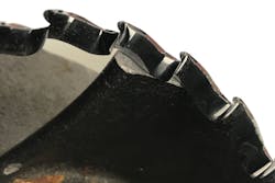
- Serrated wear plates, which are designed to push materials off the impeller tip and back into the flow stream.
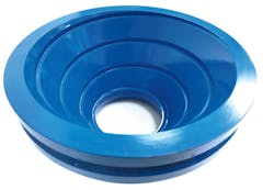
- Shoulders at the suction of the pump, which shield the impeller tip so that it does not protrude into the flow stream and has no chance for clogging.
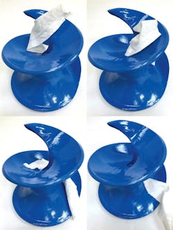
The second potential clogging location is on the leading edge of the impeller vane. In wastewater, all pump designers must deal with a tradeoff: the more vanes in the pump, the higher the efficiency that can be achieved. However, more vanes also means more chances of clogging because rags are squeezed through smaller passages and more impeller vanes pass through the eye of the impeller and into the path of oncoming potential clogs. While decreasing the amount of vanes in the impeller helps increase clog resistance, the inclusion of two or more vanes in an impeller will create multiple flow paths through the pump. Multiple flow paths within the pump mean that a rag may still get caught on the leading edge of the vane as the splitting flow pulls the rag down both sides of that impeller vane. Ideally, the best option would be to have zero vanes so that rags cannot get caught on them, but without vanes, a pump will not move any water and it becomes just a bulge in the pipeline. Single-vane pumps have only one passage through the pump, and rags that get caught on the leading edge of the vane will get pulled off the vane and back into the flow stream as the water flows through this single passage.
The third potential clogging location is in the small gap between the rotating impeller and stationary volute of the pump. All high-efficiency pumps must maintain a tight gap between the impeller and volute, which decreases recirculation within the pump and in turn, increases efficiency. This gap must be able to be maintained either through replacing wear rings or by adjusting the impeller-to-liner clearance so that efficiency can be revived as the pump wears.
For enclosed impeller pumps, this gap is maintained through a smooth wear ring on the impeller, or on the suction of the pump, or both. For open impeller pumps, this gap is maintained through an adjustable liner, which sits between the outer impeller edge and the pump volute. The small gap between the impeller and volute (or wear rings) is an ideal location for strings, hair, thin plastics and small rags to get caught.
There is no way to keep these thin materials from getting caught in this gap between the impeller and liner. Instead, the materials must be dealt with in a manner that forces them out of the gap and back into the flow stream. For these trapped materials to be forced out of the gap and reintroduced into the flow stream, the gap must be temporarily opened as the impeller rotates around. The most common method that manufacturers use to provide this temporary opening is to place a spiral-shaped groove in the liner, which sits between the impeller and volute. The purpose of the groove is to temporarily open the gap between the impeller and liner just long enough to allow trapped materials to be pulled off the edge of the impeller and back into the flow stream. The grooves should be designed small enough so they do not affect the flow rate of the pump or its efficiency, yet large enough to provide an effective temporary opening as the pump wears and is readjusted.
Note that these materials tend to build up in other locations in the pump, such as behind the impeller, but this buildup does not typically affect the pump’s performance enough to clog the pump, decrease flow, or increase power consumption.
The role of proper wastewater pump operation
The manner in which pumps are operated often plays a role in the clog resistance of a pumping system. Through careful selection of the correct pump type and system operating principles, clogs can be completely eradicated from a system. No single pump design solution (mentioned earlier) can be used by itself and expected to solve clogging problems. For example, decreasing impeller vanes without protecting the vane tip may or may not increase the clog resistance of a pump. However, the good news for all pump users is that through the use of the correct pumping technology and good operating practices, most clogging problems can be resolved satisfactorily.
Eric Tobin is technical product manager for Weir Specialty Pumps, where he has worked for more than 12 years in applications engineering, business development and product management roles. He also has experience as a pump mechanic, welder and general maintenance mechanic. Tobin brings a breadth of general pump knowledge to Weir Specialty Pumps. Tobin can be reached at eric.tobin@mail.weir or 801-530-7998.
