By Allan R. Budris
Because mechanical shaft seal failures are the number one cause of pump downtime, the writer decided to dedicate this column to mechanical seal basics.
Years ago, most pump shafts were sealed using rings of soft packing, compressed by a packing gland, but this type of shaft seal required a fair amount of leakage just to lubricate the packing and keep it cool. Then came the development of the “mechanical seal,” which accomplishes the job of restraining product leakage around the pump shaft with two very flat surfaces (one stationary and one rotating). Even though these mechanical seal faces also require some (very small) leakage across the faces, to form a hydrodynamic film, this leakage normally evaporates and is not noticeable. Most pump shafts today are sealed by means of mechanical seals. However, because of the delicate components used for this new sealing method, mechanical seal failures are the greatest cause of pump down time. This begs for a better understanding of this seal type and its application.
Main elements of a mechanical seals
All mechanical seals are constructed with the following basic sets of parts:
- A set of (very flat) machined and lapped primary sealing faces: The very close (near) contact between these two flat mating surfaces, which are perpendicular to the shaft, minimizes leakage. Dissimilar materials are usually used for the faces, one hard and one softer, in order to prevent adhesion of the two faces. One of the faces is usually a non-galling material such as carbon-graphite. The other surface is usually a relatively hard material like silicon-carbide, or ceramic. However, when handling abrasive, two hard surfaces are normally used:
- One face is held stationary in a housing
- The other face is fixed to, and rotates with the shaft.
- A set of secondary static seals, typically O-rings, wedges and/or V-rings.
- One static seal, seals stationary component(s) to the housing
- The other seal, seals the rotating component(s) to the shaft (it normally moves axially on the shaft or shaft sleeve)
- A spring member to maintain face contact, such as a single spring, multiple springs or metal bellows.
- Other mechanical seal hardware, which includes shaft sleeves, gland rings, collars, compression rings, and/or pins.
Mechanical seals require clean water, or other compatible liquid, for the lubrication of the seal faces. The faces in a typical mechanical seal are lubricated with a boundary layer of gas or liquid between the faces. Lubrication can be provided from the pumped liquid itself or from an external source, depending on system requirements.
Mechanical Seal Types
There are multiple designs available for the mechanical seal configuration. Understanding how they work will help the readers select the appropriate type for their application.
They are:
- Conventional
- Pusher
- Non-pusher
- Unbalanced
- Balanced
- Cartridge
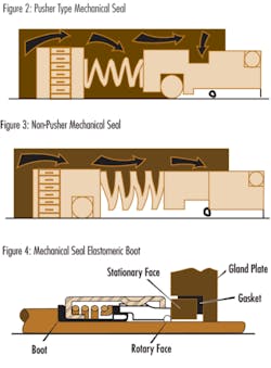
Pusher seals incorporate secondary seals that move axially along a shaft or sleeve to maintain contact at the seal faces, to accommodate wear and to assist in the absorption of shaft misalignment.
Advantages are that they are inexpensive and commercially available in a wide range of sizes and configurations.
The primary disadvantage of this seal type is that it is prone to secondary seal hang-up and fretting of the shaft or sleeve, especially when the seal is exposed to solids. A pusher seal type should not be selected if the secondary seal is likely to hang-up. Can small deposits of solids form ahead of the secondary sealing member?
The non-pusher or bellows seal does not have a secondary seal that must move along the shaft or sleeve to maintain seal face contact. In a non-pusher seal the secondary seal is in a static state at all times, even when the pump is in operation. A secondary sealing member is not required to make up the travel as the rotary and stationary seal faces wear. Primary seal face wear is typically accommodated by welded metal or elastomeric bellows which move to assist in the compression of the rotary to stationary seal faces.
The advantages of this seal type are the ability to handle high and low temperature applications (metal bellows), and that it does not require a rotating secondary seal, which means it is not prone to secondary seal hang-up or shaft/sleeve fretting. Elastomeric bellows seals are commonly used for water applications.
The disadvantages are that thin bellows cross sections must be upgraded for use in corrosive environments, plus the higher cost of metal bellows seals.
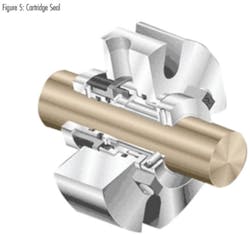
Cartridge seals have the mechanical seal pre-mounted on a sleeve (including the gland). They fit directly over the shaft or shaft sleeve, and are available in single, double, and tandem configurations. Best of class pump users give strong consideration to the use of cartridge seals.
The advantages are that this seal configuration eliminates the requirement for seal setting measurements at installation. Cartridge seals lower maintenance costs and reduce seal setting errors.
The primary disadvantage is the higher cost, plus in some cases they will not fit into existing stuffing box/seal housings.
Mechanical Seals Arrangements
Single seals do not always meet the shaft sealing requirements of today’s pumps, due to the small amount of required leakage when handling toxic or hazardous liquids; suspended abrasives or corrosives in the pumpage getting between the seal faces and causing premature wear; and/or the potential for dry operation of the seal faces. To address these situations, the seal industry has developed configurations which incorporate two sets of sealing faces, with a clean barrier fluid injected between these two sets of seal faces. The decision to choose between a double or single seal comes down to the initial cost to purchase the seal vs. the cost of operation, maintenance and downtime caused by the seal, plus the environmental and user plant emission standards for leakage from the seal.
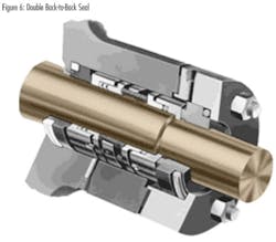
The more common multiple seal configuration is called a Double (dual pressurized) seal, where the two seal face sets are oriented in opposite directions. The features of this seal arrangement are:
- Potentially five times the life of a single seal in severe environments.
- The metal inner seal parts are never exposed to the liquid product being pumped, which means no need for expensive metallurgy; especially good for viscous, abrasive, or thermosetting liquids.
- The double seal life is virtually unaffected by process upset conditions during pump operation.
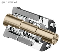
The other multiple seal configuration is called a Tandem (dual unpressurized) arrangement, where the two individual seals are positioned in the same direction. This seal arrangement is commonly used in Submersible wastewater pumps, between the pump and motor, with oil as the barrier liquid. The typical features of this seal arrangement are:
- The pressure between seals is lower than the seal chamber pressure (typically atmospheric)
- The external fluid only lubricates the most outside set of faces
- Pumped fluid lubricates most inside faces
- The outside seal serves as a safety seal or containment device
- Leakage to the atmosphere is external fluid, possibly mixed with small amounts of pumped fluid.
Mechanical Seal Selection
The proper selection of a mechanical seal can be made only if the full operating conditions are known. Identification of the exact liquid to be handled is the first step in seal selection.
- Metal parts must be corrosion resistant, usually plated steel, bronze, stainless steel, or Hastelloy.
- Mating faces must also resist corrosion and wear. Carbon, ceramic, silicon carbide or tungsten carbide may be considered.
- Stationary sealing members of Buna, EPR, Viton and Teflon are common.
Pressure:
The proper type of seal, balanced or unbalanced, is based on the pressure on the seal and on the seal size.
Temperature:
Can determine the use of the sealing members as materials must be selected to handle liquid temperature.
Characteristics of the Liquid:
Abrasive liquids create excessive wear and shorten seal life.
- Double seals, or clear liquid flushing from an external source, allow the use of mechanical seals on these difficult liquids.
- For best results with double (or tandem) seals handling abrasive, the inboard seal faces should be a hard material, such as silicon carbide vs. silicon carbide, while the outboard seal faces should have maximum lubricity, such as silicon carbide vs. carbon graphite.
Conclusions
The seal type and arrangement selected must meet the desired reliability, life cycle costs, and emission standards for the pump application. Double seals and double gas barrier seals are becoming the seals of choice. Finally, it should be noted that there are special single seal housing designs that greatly minimize the abrasives reaching the seal faces, even without an external water flush, but this is a subject for another column.
About the Author:
Allan R. Budris, P.E., is an independent consulting engineer who specializes in training, failure analysis, troubleshooting, reliability, efficiency audits and litigation support on pumps and pumping systems. With offices in Washington, NJ, he can be contacted via e-mail at [email protected].
More WaterWorld Current Issue Articles
More WaterWorld Archives Issue Articles
