When operating in exceptionally challenging conditions or handling difficult materials such as sewage and wastewater sludges, even the best designed heat exchangers will be susceptible to fouling. The impact of fouling in heat exchangers has been recognized since 1910, when the first research on the issue was conducted. Since then, there have been many developments from patented solutions to standard good practice, such as maintaining flow rates and carefully controlling temperatures. A well-designed heat exchanger will take the standard fouling factor for the material it is to handle into account at the specification stage, ensuring that sufficient heat exchange occurs when normal levels of fouling are experienced in operation.
What is fouling?
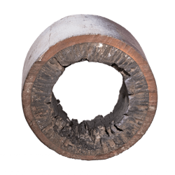
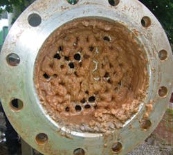
The most common definition of fouling in relation to heat exchangers is the deposition and accumulation of unwanted material such as scale, suspended solids, insoluble salts and even algae on the internal surfaces of the heat exchanger. Depending on the materials involved, this fouling can occur on both the primary and service surfaces of the exchanger, and sometimes both at once.
Heat exchanger importance
Fouling has a significant impact on heat transfer across the heat exchanger surface, and therefore on the overall operational performance and the economics of the process.
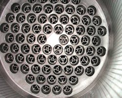
The buildup of fouling also reduces the cross-sectional area of the tubes or flow channels and increases the resistance of the fluid passing over the surface. These side effects combine to increase the pressure drop across the heat exchanger, reducing flow rates and aggravating the problem further. In the worst cases, the heat exchanger quickly becomes blocked.
Corrosion of the heat exchanger can occur depending on the fouling deposits involved, which can often be hidden by the fouling layer itself. This shortens the working life of the heat exchanger and can result in catastrophic failure.
Fouling factor
The fouling factor represents the theoretical resistance to heat flow due to the buildup of a fouling layer on the tube surfaces of the heat exchanger. In practice, fouling factors are often overstated by the end user in an attempt to minimize the frequency of cleaning. In reality, however, using the wrong fouling factor may actually result in the need for more frequent cleaning.
The fouling factor is a mathematical value (usually referred to as Rf or Rd) that represents the thermal resistance of the deposit and is effectively a ratio between the transfer coefficient of a clean heat exchanger and the same unit after fouling.
Standard values are available for a number of common liquids and gases such as fuel oil, seawater and alcohol vapor. However, for many materials, including those with the highest fouling factors such as sludges, it is best to analyze the substance to achieve an accurate result.
Signs of fouling
One of the first signs of significant fouling beyond design parameters is a loss of performance as heat transfer deteriorates. An increase in pressure drop can sometimes be seen as fouling builds up, but it is unreliable as an indicator of heat exchanger performance and is not as effective or reliable as monitoring heat transfer performance.
Types of fouling
There are different types of fouling, which can vary according to a number of factors, such as the operating conditions in which the heat exchanger is used. There are also different terms used globally for the different types of fouling and this can lead to confusion about what is actually happening in a particular situation.
In simple terms, there are four different types of fouling as follows:
Chemical fouling, or scaling, occurs when chemical changes within the fluid cause a fouling layer to be deposited onto the tube surface. A common example is scaling in a kettle or boiler caused by hardness salts depositing onto the heating elements as the solubility of the salts reduce with increasing temperature. The likelihood of scaling increases with rising temperature, concentration and pH levels. Such effects can be minimized by careful control of the tube wall temperature in contact with the fluid. Chemical fouling must be removed by either chemical treatment or mechanical descaling.
Biological fouling is caused by the growth of organisms, such as algae, within the fluid that deposit onto the surfaces of the heat exchanger. While outside the direct control of heat exchanger designers, it can be influenced by the choice of material. For example, nonferrous brass materials are poisonous to some organisms. This type of fouling is also removed by either chemical treatment or mechanical brushing processes.
Deposition fouling (also known as sedimentation fouling) occurs when particles contained within the fluid settle onto the surface, usually when the fluid’s velocity falls below a critical level. Good heat exchanger design, including the calculation of the critical velocity for any combination of fluids and particles, should result in minimum working velocities above this critical level. Mounting the heat exchanger vertically can also minimize the effect as gravity pulls any particles out of the heat exchanger away from the heat transfer surface even at low velocity levels. Deposition fouling is normally removed mechanically by brushing or scraping.
Corrosion fouling occurs when a layer of corrosion products builds up on the surfaces of the tube, forming an extra layer of material that often has thermal resistance. It should not be confused with corrosion occurring under the fouling layer as mentioned previously. The careful use of corrosion-resistant materials such as stainless steel is a key factor in preventing corrosion fouling.
Preventing and reducing fouling
In all cases, prevention is better than cure. Preventing or reducing fouling will be cheaper and more effective in maintaining heat exchanger performance than removal or cleaning.
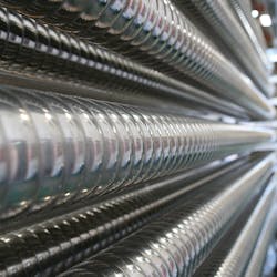
Some methods to reduce each type of fouling have already been discussed. Using corrugated tubes in heat exchanger construction, as HRS does, is beneficial in preventing both deposition fouling and chemical fouling. Deposition fouling is reduced due to greater levels of turbulence at lower fluid velocities, while chemical fouling is often reduced because the enhanced heat transfer coefficients produced by the corrugated tube result in tube wall temperatures being closer to the bulk fluid temperature of the working fluids.
The surface of the heat exchanger will also have an effect; rough surfaces are known to collect particulates, which increases fouling. The smooth, polished surfaces that can be achieved on tubes made from 304 or 316 stainless steel will also help minimize fouling.
Conclusion
While some forms of fouling are unavoidable, careful design and choice of the right heat exchanger (for example, using corrugated tubes), can go a long way to minimizing the effects. The first step should always be to analyze both the product and service fluids to calculate accurate fouling factors, and this is then followed by good design to ensure adequate fluid velocities, temperatures and other operating parameters.
The design will take into account the likelihood of fouling, the required frequency of inspection and cleaning, and will include features to make these processes as quick and simple as possible, for example, using integrated inspection panels and removable tubes.
Providing as much information at the design phase is undoubtedly the best way to keep heat exchangers running effectively for many years.
