By Fred Wiesler
Due to the increase in natural gas extraction from shale gas deposits, there is an abundance of reserves in the United States. With growing production and falling prices, exportation of natural gas has become more economically viable. In order to convert the gas drawn from these sources into a liquefied state, the gas must go through a process that separates the gases and removes water, acid gases and heavy hydrocarbons from the recovered natural gas. The gases are then cooled, transforming them to a liquefied state.
Several LNG terminals in the U.S. are adding liquefaction processes to their facilities to allow them to treat, liquefy, store and export natural gas. Liquefaction plants require a great deal of energy, and water is vital to the process.
Recently, a large LNG terminal in the U.S. required a water treatment solution to provide process water for its liquefaction operations. The water is used for injection for compressor turbines for methane, propane and ethylene, wash water for gas turbines and other utility make-up uses. The feed water to the terminal comes from a local utility and the water requires further treatment to produce high-purity water with low conductivity and silica content for the plant’s uses.
Addressing Membrane Filtration Needs
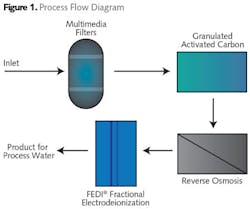
The plant selected a combination of media filtration and granular activated carbon as pretreatment to a single-pass reverse osmosis (RO) system (see Fig. 1). This pretreatment was designed to lower the turbidity and remove organics and suspended solids before membrane filtration.
The RO system consists of three single-pass trains of reverse osmosis membranes designed for two stages per train. The system is designed to remove most of the dissolved solids and ions in the water. The membranes are ion-selective and composed of thin film composite polyamide sheets.
This RO system was designed to be followed by a polishing demineralization process to obtain high purity water quality levels. Electrodeionization (EDI) was selected as the final polishing process instead of a mixed bed exchanger to reduce costs associated with regeneration, wastewater treatment and disposal. Selecting EDI also avoided the handling of corrosive chemicals and related permitting issues. In addition, it would provide constant uninterrupted high-quality feed water to the plant.
The key design element of the water treatment plant was the EDI system. EDI technologies are designed to operate with water with a hardness of less than 3 ppm to prevent scaling inside the unit. Since this plant was designed with a single-pass RO, careful selection of the EDI technology was required to ensure that the system would not require chemical regeneration and would operate without interruption. Choosing an EDI system that will operate successfully with single-pass RO feed water can result in significant capital, space, operations and maintenance savings that will make the solution effective and reliable for a long time.
The Electrodeionization Process
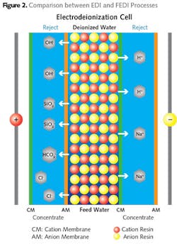
Electrodeionization (EDI) is a combination of the electrodialysis and ion exchange processes. The EDI process removes dissolved ionic impurities from water using ion-selective membranes, mixed resin media and a DC current. The ions are removed from the water through the ion-selective membrane under an electrical potential.
In this process, the anionic and cationic membranes are placed alternately with a small flow-through chamber between them. Water to be treated is passed through an alternate chamber filled with mixed resin called the dilute chamber (see Fig. 2).
The ionic impurities are drawn into the concentrate chambers as they are attracted to the electrode plates. The applied DC current also splits the water molecule at the resin bead surface into hydrogen and hydroxyl ion that continuously regenerates the exhausted resin.
Two types of ionic impurities are removed in an EDI process: strongly ionized impurities (divalent ions such as calcium, magnesium, sulfate, and monovalent ions such as sodium, chloride, and bicarbonate) and weakly ionized impurities (such as carbon monoxide, boron and silicon monoxide). Conventional EDI removes both strongly and weakly ionized impurities using a single voltage across the membrane. When operating with a single voltage, hardness must be carefully controlled to prevent scaling in the permeate chamber.
Fractional Electrodeionization (FEDI)
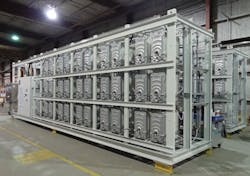
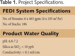
Because single-pass RO water is a challenging application for conventional EDI systems, the plant carefully evaluated options for RO permeate polishing and concluded that a QUA® Fractional Electrodeionization (FEDI®) system would be the best option (see Table).
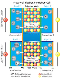
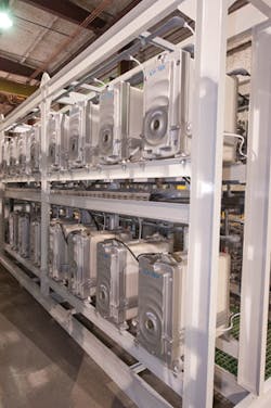
The key difference in a FEDI unit is that rather than applying one current to the entire module as in conventional electrodeionization, the FEDI process differentiates the removal of weakly ionized and strongly ionized impurities by using a two-stage process. This allows a significant portion of strongly ionized impurities, mainly the divalent ions which can cause precipitation, to be removed in the first stage. Subsequently, a higher voltage is applied for removal of weakly ionized impurities such as silica in the second stage. The rejected ions from both stages are removed using separate reject streams, preventing hardness precipitation and allowing a higher removal of silica.
In addition, the voltage applied has a direct relationship to the pH in the concentrate chamber. Hydrogen ions are more mobile compared to hydroxyl ions in water when exposed to a low voltage differential. Thus, by applying low voltage in the first stage more hydrogen ions are transported to the concentrate chamber, making the concentrate chamber acidic with a pH of 4.5 to 5.0. This low pH condition reduces scaling inside the concentrate chamber.
The second stage of the FEDI operates at a much higher voltage, which is also called the silica removal zone. Due to reduced transport of hydroxyl ion in the first stage, there are now excess hydroxyl ions present in the dilute chamber, making it alkaline. Since the pH in the dilute chamber is higher, the removal of silica is enhanced.
Both of the first- and second-stage processes are done inside a single stack within separate concentrate chambers. This FEDI dual-voltage configuration leads to highly purified water for the refinery’s uses.
System Status
The water treatment system is key to the long-term success of the terminal’s liquefaction process. The first phase of the system was successfully commissioned in fall 2015. The water treatment system has consistently provided high-quality water for the plant’s needs since startup.
QUA’s FEDI has successfully delivered a reliable electrodeionization solution coupled with a modular design that allows for easy expansion for future growth as the plant plans to expand its capacity.
About the Author: Fred Wiesler is director of sales and marketing for QUA, an innovator of advanced membrane technologies. He can be reached at [email protected].
