In all industries requiring control of liquid and gaseous streams, the proper design of a sampling system is critical in order to produce a sample that is representative of the sampled stream. This is specifically the case for utility and industrial steam generation where parts per billion (ppb) concentrations of impurities are controlled. Sample withdraw, transport, collection and handling are often major sources of errors (as high as 1,000%) that can lead to incorrect or unnecessary corrective actions (see Table 1).
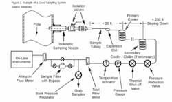
A typical sampling system consists of an isokinetic sampling nozzle (see Figure 1), two isolation valves, sample tubing, a primary cooler/condenser, a secondary sample cooler, pressure reduction and total flow regulation valves, a distributor for individual analyzers and grab samples, a back pressure regulator, and a sample drain (see Figure 2). All wetted sampling system components should be made from stainless steel to prevent the components from corroding and contaminating the sample.
What Is Isokinetic Sampling?
Isokinetic sampling ensures that all phases (solid oxides and precipitates, liquid droplets, and vapor) of the sampled fluid enter the sampling nozzle with the same velocity vector (velocity and direction of flow) and the flow velocity into the nozzle is the same as the sampled stream velocity. The main reason isokinetic sampling is necessary is that the sampled stream is almost always a two-phase fluid (gas-liquid, gas-solid, liquid-solid) and the second phase has a very different chemical composition than the steam or water. In addition, the second phase (droplets or particles) has a different density and inertia than the primary phase (gas or liquid) and therefore wouldn’t be proportionally represented in a sample that’s not withdrawn isokinetically.
Locations where isokinetic sampling nozzles should be used include: feedwater, boiler downcomer, saturated steam, and main steam (or reheat steam).
Additional Considerations
The following must be considered when designing a sampling system (see Figure 2):
- Integrity of the Sampling Nozzle - design must consider the effects of vortex shedding on vibration and strength of the nozzle attachment to the pipe in order to prevent high stresses and potential failures.
- Isolation Valves - should be rated for the application temperature and pressure and provide a minimum change of cross-section between the bore of the sampling nozzle and the valve orifice.
- Sample Tubing between the Nozzle and Primary Sample Cooler - should be as short as possible (not longer than 20 ft) to minimize pressure drop and reduce possibility of impurity deposition in the sample tubing. The inner diameter (ID) of this sample tubing should be close to the nozzle bore size to minimize changes in cross-sectional area. The tubing should form an expansion coil after the isolation valves to allow for any movement or expansion of the pipe. Sharp radius bends should be avoided.
- Primary and Secondary (if Necessary) Sample Coolers - should be of a counterflow design and be sized to ensure adequate cooling capacity, with allowances for reduced heat transfer due to scaling.
- Sample Tubing after the Primary Sample Cooler - should slope downward and have a minimum number of bends. It should be sized so the sample flow velocity is 4 to 6 ft/s in order to minimize deposition in the sample lines and to reduce the time required to achieve equilibrium between impurities in the flowing sample and the tubing.
The length of sample tubing should be as short as possible (<200 ft) to limit both pressure drop and lag time from when the sample enters the sampling nozzle to when it reaches the analyzers. Sharp radius bends in the sample tubing should be avoided.
- - not representing sampled stream (wall effects, stratification, not isokinetic, mixing, etc.)
- - not representing all phases (solid, liquid, gas)


